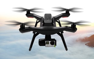
아두이노(Arduino) 환경에서 전형적인 MPU6050 센서 입력에 사용되는 칼만 필터(Kalman filter)의 예제입니다.
또한 이 칼만 필터는 가속도계(accelerometer) 혹은 지자계(magnetometer)와 그리고 자이로(gyroscope)로부터 각도(angle), 각속도(rate) 그리고 bias를 계산하는데 사용될 수 있습니다(C++ version).
https://github.com/TKJElectronics/KalmanFilter
다음은 C version입니다.
http://www.cnblogs.com/zjutlitao/p/3915786.html
Kalman.h
/* Copyright (C) 2012 Kristian Lauszus, TKJ Electronics-> All rights reserved->
This software may be distributed and modified under the terms of the GNU
General Public License version 2 (GPL2) as published by the Free Software
Foundation and appearing in the file GPL2->TXT included in the packaging of
this file-> Please note that GPL2 Section 2[b] requires that all works based
on this software must also be made publicly available under the terms of
the GPL2 ("Copyleft")->
Contact information
-------------------
Kristian Lauszus, TKJ Electronics
Web : http://www->tkjelectronics->com
e-mail : kristianl@tkjelectronics->com
*/
#ifndef _Kalman_h
#define _Kalman_h
struct Kalman {
/* Kalman filter variables */
double Q_angle; // Process noise variance for the accelerometer
double Q_bias; // Process noise variance for the gyro bias
double R_measure; // Measurement noise variance - this is actually the variance of the measurement noise
double angle; // The angle calculated by the Kalman filter - part of the 2x1 state vector
double bias; // The gyro bias calculated by the Kalman filter - part of the 2x1 state vector
double rate; // Unbiased rate calculated from the rate and the calculated bias - you have to call getAngle to update the rate
double P[2][2]; // Error covariance matrix - This is a 2x2 matrix
double K[2]; // Kalman gain - This is a 2x1 vector
double y; // Angle difference
double S; // Estimate error
};
void Init(struct Kalman* klm){
/* We will set the variables like so, these can also be tuned by the user */
klm->Q_angle = 0.001;
klm->Q_bias = 0.003;
klm->R_measure = 0.03;
klm->angle = 0; // Reset the angle
klm->bias = 0; // Reset bias
klm->P[0][0] = 0; // Since we assume that the bias is 0 and we know the starting angle (use setAngle), the error covariance matrix is set like so - see: http://en->wikipedia->org/wiki/Kalman_filter#Example_application->2C_technical
klm->P[0][1] = 0;
klm->P[1][0] = 0;
klm->P[1][1] = 0;
}
// The angle should be in degrees and the rate should be in degrees per second and the delta time in seconds
double getAngle(struct Kalman * klm, double newAngle, double newRate, double dt) {
// KasBot V2 - Kalman filter module - http://www->x-firm->com/?page_id=145
// Modified by Kristian Lauszus
// See my blog post for more information: http://blog->tkjelectronics->dk/2012/09/a-practical-approach-to-kalman-filter-and-how-to-implement-it
float P00_temp;
float P01_temp;
// Discrete Kalman filter time update equations - Time Update ("Predict")
// Update xhat - Project the state ahead
/* Step 1 */
klm->rate = newRate - klm->bias;
klm->angle += dt * klm->rate;
// Update estimation error covariance - Project the error covariance ahead
/* Step 2 */
klm->P[0][0] += dt * (dt*klm->P[1][1] - klm->P[0][1] - klm->P[1][0] + klm->Q_angle);
klm->P[0][1] -= dt * klm->P[1][1];
klm->P[1][0] -= dt * klm->P[1][1];
klm->P[1][1] += klm->Q_bias * dt;
// Discrete Kalman filter measurement update equations - Measurement Update ("Correct")
// Calculate Kalman gain - Compute the Kalman gain
/* Step 4 */
klm->S = klm->P[0][0] + klm->R_measure;
/* Step 5 */
klm->K[0] = klm->P[0][0] / klm->S;
klm->K[1] = klm->P[1][0] / klm->S;
// Calculate angle and bias - Update estimate with measurement zk (newAngle)
/* Step 3 */
klm->y = newAngle - klm->angle;
/* Step 6 */
klm->angle += klm->K[0] * klm->y;
klm->bias += klm->K[1] * klm->y;
// Calculate estimation error covariance - Update the error covariance
/* Step 7 */
P00_temp = klm->P[0][0];
P01_temp = klm->P[0][1];
klm->P[0][0] -= klm->K[0] * P00_temp;
klm->P[0][1] -= klm->K[0] * P01_temp;
klm->P[1][0] -= klm->K[1] * P00_temp;
klm->P[1][1] -= klm->K[1] * P01_temp;
return klm->angle;
}
// Used to set angle, this should be set as the starting angle
void setAngle(struct Kalman* klm, double newAngle) { klm->angle = newAngle; }
// Return the unbiased rate
/* These are used to tune the Kalman filter */
void setQangle(struct Kalman* klm, double newQ_angle) { klm->Q_angle = newQ_angle; }
/* Default value is (0.003f), raise this to follow input more closely, lower this to smooth result of kalman filter */
void setQbias(struct Kalman* klm, double newQ_bias) { klm->Q_bias = newQ_bias; }
void setRmeasure(struct Kalman* klm, double newR_measure) { klm->R_measure = newR_measure; }
double getQangle(struct Kalman* klm) { return klm->Q_angle; }
double getQbias(struct Kalman* klm) { return klm->Q_bias; }
double getRmeasure(struct Kalman* klm) { return klm->R_measure; }
#endif
'Flight Controller 이해 > 비행제어기(FC)' 카테고리의 다른 글
| 보상 필터(Complementary filter) (0) | 2017.12.03 |
|---|---|
| MPU6050의 칼만 필터(Kalman filter)의 구현 예제(3) (0) | 2017.11.27 |
| MPU6050의 칼만 필터(Kalman filter)의 구현 예제(2) (1) | 2017.11.25 |
| MPU6050의 칼만 필터(Kalman filter)의 구현 예제(1) (1) | 2017.11.20 |
| 칼만 필터(Kalman filter) (0) | 2017.03.15 |

 Kalman.h


