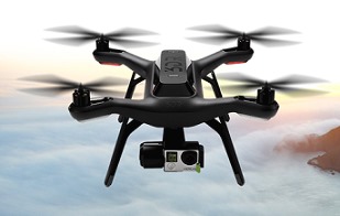
AutoQuad는 오픈 소스 펨웨어 프로젝트입니다. 따라서 누구나 프로젝트를 다운로드 받아 수정하거나 개선하여 자신의 드론(Drone)에 업데이트 할 수 있고 자신의 구미에 맞게 비행을 즐길 수 있습니다.


AutoQuad 홈페이지에서 Source Code를 확인하는 법 ]


1) 메뉴에서 'Forum'를 클릭합니다. 

AutoQuad Forum


2) 메뉴에서 'AQ Downloads'를 클릭합니다.

AutoQuad and ESC32 Downloads


3) 다음 그림과 같이 하단의 아이콘 모음에서 선택합니다.


4) 모든 Source Code를 'Find file'을 클릭하여 확인하거나 다운로드 할 수 있습니다.


'Radio Control > Flight Controller' 카테고리의 다른 글

비행제어기(FC)란?  (0) 2017.03.07
AutoQuad 6 비행제어기의 스펙  (0) 2015.12.02
AutoQuad란?  (0) 2015.11.29
APM v2.5 vs. Crius AIOP  (0) 2014.03.04
다양한 Multiwii 보드  (0) 2014.03.03
Posted by Nature & Life


ESC(electronic speed controller)를 설계할 때 왜 STM32가 유리한가요?


  • High side와 low side에 PWM이 automatic dead-time이 추가를 허용하는 일차적인 FET 제어기로서 TIM1을 사용할 수 있고 다른 이득 등을 제공합니다.

  • 저 비용의 개발 툴

In-Circuit Debugger/Programmer

  • 컴파일러로써 ARM GCC

  • SWD 프로그래밍/디버깅

  • I2C, CAN 지원

  • PWM 제어

  • 클럭 정밀도

정밀한 클럭은 일부 외장 오실레이터(oscillator) 타입을 요구합니다. STM32 내부 오실레이터의 정밀도는 1% 이내입니다. 이는 closed loop 실제 속도, PWM 주파수 정밀도 그리고 timing에 연관된 어떤 보고된 값들에 영향을 줍니다. 또한 이는 UART 최대 통신 속도에 어떤 밀접한 관계를 갖을 것입니다.

일차적인 클럭 속도는 72MHz의 외장 부품을 사용할 수 있지만 내부 오실레이터를 사용할 때 64MHz로 제한됩니다. 이는 64MHz에서 보드상에 프로세싱 파워가 충분하기 때문에 문제가 되질 않습니다.

  • UART

오픈 소스 커뮤너티에서 요구하는 것처럼 USART에 완전한 FTDI 접근을 합니다. 이를 사용하여 CLI(시리얼 터미널과 같은 Command Line Interface)가 구현될 수 있습니다.

  • 모든 FET 상에 게이트 저항

이는 FET turn-on 특성에 정밀한 제어를 할 수 있습니다. FET를 천천히 켜는 것(높은 게이트 저항)은 FET 상에 손실을 증가시킵니다. 그러나 전압 버스에 고주파 잡음을 엄청나게 줄일 수 있습니다. FET를 빠르게 켜는 것(낮은 게이트 저항)은 FET의 손실을 감소시키지만 전압 버스 상에 엄청난 잡음을 증가시킬 것입니다. 이것은 마이크로컨트롤러의 reset, 버스 커패시터 사이즈 그리고 다른 잡음 관련된 설계 결정 이슈에 큰 영향을 줍니다. Dead-time에 관련하여 너무 짧다면, 느린 FET는 실제로 위험할 수 있습니다.

  • 최근에 AVR 시리즈와 같이 STM32 시리즈도 Arduino 환경을 지원합니다.

  • 특히 Cortex M4 경우에 100% C 언어 프로그램이 가능합니다. 고성능의 high end 급의 소형 마이크로컨트롤러로 RISC, Pipeline 등의 구성으로 사실상 assembly 코딩이 불가능하지만, 다른 마이크로컨트롤로 달리 C 언어를 완벽하게 지원하여 assembly의 이해가 필요 없다는 것입니다. 기존의 마이크로컨트롤러는 C 언어를 지원하여도 최상의 성능을 위해서는 assembly 코딩이 불가피하지만 Cortex M4는 의미가 없으며 C 언어에서 지원하지 않은 명령어에 대해서는 intrinsic 함수로 assembly 코드로 1:1 변환하며, 디버깅 시에 C 언어 소스 코드가 의도한 assembly 코드로 올바르게 컴파일 되었는지 확인할 수 있는 정도의 assembly 언어 지식이 요구됩니다.


'Embedded Programming > STM32 Cortex-M4' 카테고리의 다른 글

STM32 MCU 누클레오 보드  (0) 2018.01.12
Discovery vs. Nucleo board  (1) 2018.01.11
STM32F4 시리즈의 소자 구별 방법  (0) 2018.01.03
STM32F405xx 스펙 요약  (0) 2017.11.17
AVR vs. STM32 comparison for Drone  (0) 2015.12.04
Posted by Nature & Life


ARM 기반에 32 비트 MCU(STM32 계열)을 사용하여 비행제어기 보드(Flight Control Board)와 ESC를 만든 AutoQuad 프로젝트를 소개합니다. MCU가 갖는 빠르고 강력한 이점 외에도 C언어 기반의 ESC를 포함한 완전한 오프 소스 프로젝트라는 것입니다.


AutoQuad is an Open Source firmware project with closed source hardware. It is aimed at providing a flight controller board with stabilization, dynamic flight and autopilot features. The community can enhance the AutoQuad code. The powerful hardware with a 32 bits MCU and a selection of the best IMU sensors form the base for the AutoQuad flight controller, the possibilities are endless and only limited by the imagination and skills of the coders.


AutoQuad는 비공개 하드웨어를 사용한 오픈 소스 펨웨어 프로젝트입니다. 이는 안정성과 역동적인 비행 그리고 자동 항법 특징을 갖는 비행 제어 보드를 공급하는데 목적이 있습니다. 이 커뮤니티는 AutoQuad 코드를 진보시킬 수 있습니다. 32 비트 MCU와 가장 훌륭한 IMU 센서들의 장착한 강력한 하드웨어로 AutoQuad 비행제어기의 기본을 갖추었습니다. 그 가능성은 무한하고 단지 코드를 프로그램하는 사람의 상상력에 의해서 제한될 뿐입니다.


The current code base is targeting multicopters up to 14 motors. However the platform is flexible and can be adapted to fixed wing or single rotor applications.


현재의 코드는 14 모터까지 장착한 멀티콥터를 목표로 합니다. 그러나 개발환경은 유연하고 고정익 혹은 단일 로터를 갖는 기체에도 적용될 수 있습니다.


AutoQuad has recognized the need for specially adapted speed controllers or ESC’s. During the initial project setup, an 32bit ESC is developed: the ESC32. As with AutoQuad, the ESC32 is based on open source code, but closed source hardware.


AutoQuad는 특별한 속도 제어기 혹은 ESC를 요구해왔습니다. 초기 프로젝트 착수 동안에 32 비트 ESC가 개발되었습니다: ESC32. AutoQuad와 함께 사용되어지기 때문에 ESC32는 오픈 소스 코드 기반이지만 비공개 하드웨어에 사용되어집니다.


다음은 실제 프로젝트의 로드맵(Actual Project Timeline)니다.

Actual Project Timeline


'Radio Control > Flight Controller' 카테고리의 다른 글

AutoQuad 6 비행제어기의 스펙  (0) 2015.12.02
AutoQuad 사이트에서 소소 코드를 확인하는 법  (0) 2015.12.02
APM v2.5 vs. Crius AIOP  (0) 2014.03.04
다양한 Multiwii 보드  (0) 2014.03.03
Multiwii란?  (0) 2014.02.26
Posted by Nature & Life
Radio Control/etc2015. 4. 30. 18:38


사람마다 멀티콥터(Multicopter)를 즐기는 방법은 크게 2가지가 있습니다.


● 레저활동으로 다이나믹한 조종비행과 고공촬영을 즐기는 매니아 층

● 멀티콥터를 직접 제작부터 비행까지 취미생활을 영위하는 매니아 층


자신이 단순히 레저활동으로 비행을 즐기고 촬영을 감상하는 매니아 층이라면 Flight Controller(FC)를 포함한 상업용 완전한 기체(RTF)를 구입하여 바로 비행에 나서는 것이 시간을 단축시키는 길입니다. 그러나 Flight Controller의 구성(GPS 등) 및 펌웨어(Firmware) 등을 수정하며 조립과정에서부터 비행까지 직접 관여하며, 프론티어 정신에 비중을 두는 매니아 층이라면 완전한 기체(RTF)보다는 반조립 기체(ARF)에 자신이 직접 제작한 Flight Controller 등을 탑재하길 원할 것입니다.


만일 후자의 경우라면 전자와 다르게 고려해야 될 것이 많이 있습니다. 대부분의 상업용 기체는 Rock solid한 반면에 자작용 기체는 유연하지만 안정성이 떨어질 수 밖에 없다는 것입니다. 'Rock soild'라 함은 제조사에서 무수한 시행착오로 고도로 최적화되어 있어 안정한 비행이 가능하다는 것이고, 후자는 하드웨어적 유연성으로 인해 혹은 여러 부품과의 호환성으로 인해 안정성은 결국 유저 자신의 몫이라는 것입니다.


하지만 후자의 경우 여러 장점도 있습니다. 상업용 기체는 안정성을 담보로 로열티에 대한 댓가를 치루어야 합니다. 즉 비싸다는 것입니다. 그러나 후자는 기체만을 구입하고 Flight Controller 등은 Open source 이기에 저렴하다보니 조립하는 것이 [반드시 그렇지는 않지만] 싸질 수 있다는 것입니다. 자신의 드론(Drone) 제작에 앞서 드론을 정복하기 위해서는 많은 관련지식과 시행착오를 겪어야 하며 때론 추가의 비용과 많은 시간이 걸릴 수도 있다는 것을 기억해야 합니다.


멀티콥터를 제작하려면 우선 Flight Controller를 선택해야 합니다. Open source로는 크게 Multiwill와 APM 시리즈가 있는데 두터운 사용자 층을 고려한다면 Multiwill가 추천되는 추세입니다. 이는 Community가 보다 활성화되어 있어 조립과정 중에 혹은 기체 셋팅 중에 발생할 수 있는 문제를 쉽게 해결할 수 있다는 것입니다. 기타 Open source를 골라야 한다면 원론적으로 메인 칩셋부터 확인해야 할 것입니다. 왜냐면 단적으로 STM시리즈의 마이크로컨트롤러(Microcontroller)에 익숙하지 않다면 수정은 고사하고 코드를 읽기조차 힘들기 때문입니다.


Multiwill은 Community에서 지속적으로 업데이트되고 있으며 포럼에서 많은 도움을 받을 수 있으며 코드의 수정과 업로드하는 과정을 간단화시킨 근래의 아두이노(Arduino) 환경에서 쉽게 개발할 수 있기 때문입니다. 게다가 메인 칩셋은 Atmel사의 칩으로 C언어로 최적화가 잘되는 마이크로컨트롤러로 알려지며 폭넓게 사용되고 사용자 층이 넓기 때문입니다.


어떤 매니아는 ESC조차도 자작을 시도하는데 이 경우를 제외하면 기체는 Brushless 모터를 포함한 프롭과 ESC, 프레임을 모두 갖춘 보급형 퀴드콥터 기체가 입문자로서 적당할 것입니다. F450 ARF 기체는 중국 DJI사(http://www.dji.com) 제작한 쿼드콥터 기체로 그래도 저렴한 편이며, 최근에 많이 보급되어 프레임이 견적으로 이어지면 쉽게 교환할 수 있는 장점이 있습니다.


Phantom 3


또한 F550 ARF는 헥사콥터(엄밀하게 6개의 Arm을 가짐) 기체용이며 DJI사는 자사의 Naza 시리즈 Flight Controller를 탑재하여 Phantom 시리즈로 조립, 발매하고 있습니다. F450 ARF 기체는 Flight Controller와 송/수신기, 밧데리 등은 제외하고 있으며 스펙은 다음과 같습니다.

    • Frame Weight(기체 무게) : 282g

    • Diagonal Wheelbase(대각선 기체 길이) : 450mm

    • Takeoff Weight(이륙 중량) : 800g ~ 1200g

    • Propeller : 10 x 4.5inch

    • Battery : LiPo(3S 1500mAh ~ 2600mAh)

    • Motor : 2212 ~ 2216(stator size)

    • ESC : 15A ~ 25A


F450 ARF 기체의 외형


F450 ARF 기체의 구성


'Radio Control > etc' 카테고리의 다른 글

Power Distribution Board란?  (0) 2017.03.08
Posted by Nature & Life
Radio Control/ESC2014. 6. 19. 11:52


다음은 Simon Kirby(http://0x.ca/)의 오픈 RapidESC 펌웨어 개발 사이트입니다.


https://github.com/sim-/tgy


This tree contains Atmel AVR assembly code for ATmega-based 3-phase sensor-less motor electronic speed control (ESC) boards, originally for Turnigy and similar models. This work is based on Bernhard Konze's "tp-18a" software, which was a port from his earlier personal work to the TowerPro 18A and original (not current!) Turnigy Plush boards. Please see tgy.asm for Bernhard's license.

이 목록은 ATmega 기반의 3상 브러쉬리스 모터 전자 속도 제어기(ESC) 보드를 위한 Atmel AVR 어셈블리 코드를 포함합니다. 원래는 Turnigy와 유사한 모델을 위한 것이었습니다. 이 프로젝트는 Bernhard Konze의 'tp-18a' 소프트웨어에 기반을 둡니다. 이것은 TowerPro 18A과 원래의 Turnigy Plush 보드의 그의 앞선 개인적인 프로젝트를 포트(port)한 것이었습니다. Bernhard의 라이센스에 대해서 tgy.asm을 보시기 바랍니다.


Patches and comments are always welcome! Let me know how it goes!

패치와 주석은 항상 환영합니다. 알려주세요!


Features

    • 16MHz operation on most boards

    • 16-bit output PWM with full clock rate resolution (~18kHz PWM with a POWER_RANGE of 800 steps)

    • 24-bit timing and PWM pulse tracking at full clock rate resolution

    • ICP-based pulse time recording (on supported hardware) for zero PWM input control jitter

    • Immediate PWM input to PWM output for best possible multicopter response (but NOT where soft start or really any significant current limiting is needed!)

    • Accepts any PWM update rate (minimum ~5microseconds PWM low time)

    • Optimized interrupt code (very low minimum PWM and reduced full throttle bump)

    • Configurable board pin assignments by include file

    • Smooth starting in most cases

    • Forward and reverse commutation supported, including RC-car style reverse-neutral-forward PWM ranges, with optional braking


Hardware

See http://wiki.openpilot.org/display/Doc/RapidESC+Database and/or https://docs.google.com/spreadsheet/ccc?key=0AhR02IDNb7_MdEhfVjk3MkRHVzhKdjU1YzdBQkZZRlE for a more complete list. Some board pictures here: http://0x.ca/sim/esc/

http://wiki.openpilot.org/display/Doc/RapidESC+Database 그리고/또는 좀더 완전한 목록을 위해서 https://docs.google.com/spreadsheet/ccc?key=0AhR02IDNb7_MdEhfVjk3MkRHVzhKdjU1YzdBQkZZRlE을 보시기 바랍니다. 일부 보드의 그림은 여기에 있습니다: http://0x.ca/sim/esc/


Tested boards by target:

    • afro2:

        • AfroESC 2 (prototype)

    • afro_hv:

        • AfroESC HV (high voltage, with all-N FETs and drivers)

    • afro_nfet:

        • AfroESC with all-N FETs (revision 3)

    • birdie70a:

        • Hobby King Birdie 70A (BIRD-60A)

        • Hobby King Red Brick 200A (RB200A, black board)

    • bs:

        • Hobby King 6A (HK_261000001)

        • Hobby King 10A (HK_261000002)

        • Hobby King 40A (F-40A)

        • Hobby King 60A (F-60A)

    • bs_nfet:

        • Hobby King 20A (F-20A)

        • Hobby King 30A (F-30A)

    • bs40a:

        • Hobby King BlueSeries 40A (and some Mystery 40A boards)

    • dlu40a:

        • Pulso Advance Plus DLU40A with opto-isolated inverted PWM input

        • Hobby King Multistar 45A

    • dlux:

        • Turnigy dlux 20A SBEC

    • hk200a:

        • Hobby King SS Series 190-200A (HK-SS200ALV)

        • RCTimer 50A TQFP version

    • kda:

        • Keda 12A rev B with inverted PWM input (30A should also work)

        • Dynam 18A, 25A with Blue Heat Shrink

        • Hobby King Multistar series (30A and under)

    • maytech30a:

        • Maytech 30A and 20A, complementary PWM

    • maytech40a:

        • Maytech 40A, complementary PWM

    • maytech60a:

        • Maytech 60A, complementary PWM

    • mkblctrl1:

        • MikroKopter BL-Ctrl v1.x (flashable by ISP only)

    • rb50a.hex

        • Hobby King Red Brick 50A (RB50-ESC)

    • rb70a.hex

        • Hobby King Red Brick 70A (RB70A)

        • Hobby King Red Brick 200A (RB200A-BTO, black board)

    • rct50a:

        • RCTimer 50A older MLF version

    • tbs:

        • Team BlackSheep TBS 30A ESC (ICP input version)

    • tp:

        • Original TowerPro 17A, 25A

        • Hobby King SS models without "-HW" in part number

    • tp_8khz:

        • tp at 8kHz PWM (workaround for DYS/HK-SS clones with PWM noise problems)

    • tp_i2c:

        • tp modified for I2C input (old ADC4 routed to ADC1)

    • tp_nfet:

        • Newer TowerPro 25A with inverted low side (BL8003 drivers)

    • tp70a:

        • TowerPro 70A with BL8003 FET drivers (inverted low side)

        • tgy (these boards typically have no external resonator):

        • Original TowerPro 18A

        • Original Turnigy Basic and Turnigy Plush 10A, 18A, and 25A (Hobbywing OEM)

        • RCTimer 10A, 18A, 20A, 30A, 40A (18A, 20A, 30A are same board with more or less FETs)

        • Hobby King SS models with "-HW" in part number

    • tgy6a:

        • Original Turnigy Plush 6A


Turnigy Plush 18A


Notes

    • If it breaks, you get to keep both pieces! (만일 부러지면, 두 조각을 그대로 유지하면 됩니다!)

    • Use at your own risk, and always test first without propellers! (손상을 감안해야 하며 항상 프롭 없이 테스트를 먼저 해야 합니다!)

    • New Turnigy Plush, Basic, Sentry and Pentium boards (Hobbywing OEM) have all switched to SiLabs C8051F334, d'oh! (새로운 Turnigy Plush, Basic, Sentry 그리고 Pentium 보드들(Hobbywing OEM)은 모두 SiLabs사의 C8051F334으로 전환한 상태입니다.)

    • If your ESC has 6 pads and an AVR, it's probably compatible; the pads are MOSI, MISO, SCLK, GND, VCC, and RESET. If it has 4 pads, it is probably a newer SiLabs-based one, for which this code will not work. (Except HK_261000001 which has 4 pads but has an AVR.) (여러분의 ESC가 6개의 패드와 AVR을 사용한다면 아마도 호환가능할 것입니다; 패드는 MOSI, MISO, SCLK, GND, VCC, 그리고 RESET입니다. 만일 4개의 패드를 가지고 있다면, 아마도 이것은 이 코드에서 동작하지 않는 새로운 SiLabs 칩을 사용하는 보드일 것입니다.(HK_261000001는 예외로 4개의 패드를 갖지만 AVR을 사용합니다))

    • I build and maintain this in Linux with AVRA (1.3.0 or newer). Patches welcome for AVR Studio APS files, etc. (저는 AVRA (1.3.0 or newer)로 Linux 상에서 컴파일하였습니다. AVR Studio *.aps 파일의 패치 또한 환영합니다.)

    • The TowerPro/Turnigy Plush type boards typically do not come with external oscillators, which means their frequency drifts a bit with temperature and between boards. Multicopters and RC-car/boat controllers (with a neutral deadband) would probably be better on a board with an external oscillator. The Mystery/BlueSeries boards typically have them, as well as most higher current boards. (TowerPro/Turnigy Plush 타입의 보드는 전형적으로 외장 오실레이터를 갖지 않는데 이것은 ESC의 주파수가 온도와 보드 사이에서 약간 변동될 수 있음을 의미합니다. (데드밴드를 가진) 멀티콥터와 RC자동차/보트 콘트롤러는 아마도 외장 오실레이터를 가진 보드에서 더 좋을 수 있습니다. Mystery/BlueSeries 보드는 전형적으로 외장 오실레이터를 가집니다. 게다가 가장 높은 전류를 갖는 보드입니다.)

    • This doesn't yet check temperature or battery voltage. This is not desired on multi-rotor platforms; however, people still want to use this on planes, cars, boats, etc., so I suppose I'll add it. (이것은 아직 온도와 밧데리 전압을 체크하지 않습니다. 이것은 멀터로터 플랫폼에서 요구되는 것이 아닙니다; 그러나 사람들이 비행기나 자동차, 보트 등에 이를 사용하기를 원한다면 저는 이 기능을 추가할 수 있습니다)


'Radio Control > ESC' 카테고리의 다른 글

PX4ESC의 스펙  (0) 2015.12.08
ESC32의 스펙  (0) 2015.12.04
RapidESC FAQ's  (0) 2014.06.11
RapidESC Flashing  (0) 2014.06.03
RapidESC란?  (0) 2014.05.26
Posted by Nature & Life
Radio Control/ESC2014. 6. 11. 17:11


다음은 RapidESC의 FAQ입니다.


Do I need to program the flashed ESCs?

이미 프로그램된 ESC를 프로그램해야 하는지요?


On a normal ESC it's advised to program them as below for a multirotor:

정상적인 ESC 경우에, 멀티로터(multirotor)에 대해서 아래와 같은 항목을 프로그램하는 것이 권고됩니다.


  • Battery Type: Lipo /NiXX

  • Brake: On / Off

  • Voltage Protection: Low / Mid / High

  • Protection mode: Reduce power / Cut off power

  • Timing: Auto / High / Low

  • Startup: Fast / Normal / Soft

  • PWM Frequency: 8k / 16k

  • Helicopter mode: Off / 5sec / 15sec (Start up delay)


Once your ESCs are flashed, this is not longer necessary. The necessary settings are all embedded in the flashed software.

일단 여러분의 ESC가 프로그램되면, 이것은 더이상 필요하지 않습니다. 필요한 설정은 프로그램된 소프트웨어에 모두 포함됩니다.


The throttle range however is still programmed like most standard ESCs. Start the ESC with full throttle, wait for the beeps and lower the throttle to 0.

스로틀 범위는 그러나 가장 표준 ESC와 같이 여전히 프로그램됩니다. 최대 스로틀에서 ESC를 시작하고 비프음을 기다리세요 그리고 스로틀이 '0'이 될때까지 낮추어 보세요.


'Radio Control > ESC' 카테고리의 다른 글

ESC32의 스펙  (0) 2015.12.04
RapidESC, 오픈 소스 펌웨어 개발 사이트  (0) 2014.06.19
RapidESC Flashing  (0) 2014.06.03
RapidESC란?  (0) 2014.05.26
Wii-ESC에 대한 FAQ  (0) 2014.04.07
Posted by Nature & Life
Radio Control/ESC2014. 6. 3. 12:35


How is it done?

어떻게 프로그래밍 하는지요?

The process is popularly called flashing. It's actually quite similar to the firmware update from the OpenPilot product through the USB cable and the Ground Control Software.
이 과정은 'flashing'이라고 부릅니다. OpenPilot 제품을 USB 케이블과 지상 제어 스프트웨어(Ground Control Software)를 이용하여 펌웨어를 업데이트 하는 것과 실제로 매우 유사합니다.

The ESC must be connected to the computer via an interface adapter. Afterwards, new software is installed onto the ESC via your computer. Unfortunately, the ESC is not equipped with a standard USB connection port. nor was it intended to be upgraded by the user, so a few little tricks are needed to upgrade the software. This document will illustrate how to successfully upgrade your ESC.
ESC는 인터페이스 어댑터를 통하여 컴퓨터로 연결되어야 합니다. 후로 새로운 소프트웨어가 여러분의 컴퓨터를 통해서 설치됩니다. 불행하게도 ESC는 표준 USB 연결 포트와 잘 연결되도록 갖추고 있지 않으며, 사용자에 의해서 업그레이드를 허용하지도 않습니다. 그래서 작은 트릭이 소프트웨어를 업그레이드 하기 위해서 요구됩니다. 이 문서는 어떻게 여러분의 ESC를 성공적으로 업그레이드 하는 지를 설명할 것입니다.


Risks:
Please note that there is always a possibility you will damage your ESC. Loading the wrong firmware may damage your ESC permanently. The upgrade should be done at your own risk.
여러분의 ESC를 손상시킬 수 있는 가능성이 항상 존재함을 기억하세요. 올바르지 못한 펌웨어를 탑재하는 것은 여러분의 ESC를 영구적으로 손상시킬 수 있습니다. 업그레이드는 전적으로 여러분의 책임입니다.

Compatible ESCs
호환되는 ESC들

The first step is to check whether your ESC can actually be upgraded. At the time of ths writing, only ESCs with an ATMEL micro controller can be upgraded. ESCs equipped with a SiLabs micro controller, which are mainly recent HobbyWing ESCs, cannot currently be upgraded.
처음 단계는 여러분의 ESC가 실제 업그레이드 될 수 있는지 확인하는 것입니다. 이 글을 쓰는 시점에서 ATMEL MCU로 만들어진 ESC만 업그레이드 될 수 있습니다. 주로 최근에 HobbyWing ESC에 사용되고 있는 SiLabs MCU를 실장한 ESC는 현재 업그레이드 할 수 없습니다.

Close up from a Hobbyking 18A ESC with a Atmel micro controller. 

Atmel MCU를 실장한 Hobbyking 18A ESC의 확대사진


An ESC with this version of MCU can normally be upgraded.
이 버젼의 MCU는 정상적으로 업그레이드가 가능합니다.

Close up from a Hobbywing 6A ESC with a SiLabs micro controller.

SiLabs MCU를 실장한 Hobbywing 6A ESC의 확대사진


An ESC with this version of MCU is typically accompanied with 4 contacts or programming points and cannot be upgraded.
이 버젼의 MCU를 실장한 ESC는 전형적으로 4개의 접점 혹은 프로그래밍 포인트를 가지므로 업그레이드를 할 수 없습니다.

Please note that the latest Hobbywing ESCs are no longer sold with an Atmega microprocessor. While earlier versions of these ESCs are equipped with an Atmga MCU and can be upgraded, newer versions cannot be upgraded. The only way of knowing if you have an Atmel processor on your ESC is removing the protective heat shrink and verifying the MCU type. If the MCU is an Atmel like in the above noted picture, then it should be possible to upgrade the ESC.
가장 최근의 Hobbywing ESC들은 더 이상 Atmega MCU를 실장하지 않음을 주의하세요. 반면에 이들 ESC의 초기 버젼들은 Atmega MCU를 내장하여 업그레이드가 가능하고, 새로운 버젼들은 업그레이드 할 수 없습니다. 여러분이 여러분의 ESC가 Atmel 프로세스를 내장하는지를 아는 유일한 방법은 protective heat shrink(외부 포장재)를 제거하고 MCU 형태를 파악하는 것입니다. 만일 MCU가 위에서 언급된 그림에서와 같이 Atmel이라면 그 때 ESC를 업그레이드 하는 것은 가능할 것입니다.

Check your ESC
여러분의 ESC를 확인하세요

The only way to check whether your ESC is compatible and flash new firmware is to remove the protection. Caution here... you can damage the components on the ESC if you are not careful. In the following slideshow an X-acto knife is used to cut the protective shrink tube. Carefully cut along the side of the PCB and do not damage the components.
여러분의 ESC가 호환되고 새로운 펌웨어를 프로그램할 수 있는지는 확인하는 유일한 방법은 보호필름(외부 포장재)을 제거하는 것입니다. 여기서 주의해야 할 것은 여러분이 ESC상에 부품들에 손상을 줄 수 있다는 것입니다. 다음의 슬라이드에서 X-acto 칼이 보호필름 튜브를 자르는데 사용됩니다. PCB의 측면을 따라서 주의롭게 자르고 부품을 손상시키지 않습니다.


The micro controller should be an Atmel controller, it is regularly accompanied with 6 contact points, but this is not necessarily a requirement.
MCU는 Atmel 콘트롤러이어야 합니다. 이것은 보통 6개의 접점 포인트를 가지지만 반드시 있는 것은 아닙니다.


Please refer to the  RapidESC Database to verify if your ESC is compatible.
여러분의 ESC가 호환되는지는 알아보기 위해서 RapidESC 데이터베이스를 참고하시기 바랍니다.


'Radio Control > ESC' 카테고리의 다른 글

RapidESC, 오픈 소스 펌웨어 개발 사이트  (0) 2014.06.19
RapidESC FAQ's  (0) 2014.06.11
RapidESC란?  (0) 2014.05.26
Wii-ESC에 대한 FAQ  (0) 2014.04.07
Wii-ESC 프로젝트의 소개입니다  (0) 2014.04.04
Posted by Nature & Life
Radio Control/ESC2014. 5. 26. 19:11


RapidESC는 Multicopter를 즐기는 DIY 매니아층에서 잘 알려진 이름으로 상업적인 ESC를 말하는 것은 아니며, 기존의 상업적인 ESC들의 최적화된 하드웨어에 Multicopter에서 사용할 목적으로 여러가지 성능이 향상된 펌웨어를 다시 탑재한 ESC를 말합니다.

다음은 RapidESC의 사이트에서 말하는 RapidESC는 무엇인지를 번역하여 올리니 참고하시기 바랍니다.

http://wiki.openpilot.org/display/Doc/RapidESCs


The RapidESC initiative was started to give an honest source of information regarding pre-made and re-flashed ESCs that are modified for extremely high performance on MultiCopters.

RapidESC에 대한 동기는 Multicopter 상에서 매우 향상된 성능을 갖도록 개선하여 미리 만들어지고(pre-made) 다시 프로그램하기(re-flashed) 위해 필요한 정보를 제공하기 위해서 시작되었습니다.


The OpenPilot Team and developers such as Simon Kirby have been working hard to create Open Source firmware that offers the Rapid ESC response performance which greatly enhances multirotor performance.

Simon Kirby와 같은 OpenPilot 팀과 개발자들은 Multirotor의 성능을 크게 향상시키는 빠른 ESC 응답 성능을 갖는 오픈 소스 펌웨어를 만들기 위해서 열심히 연구해왔습니다.


What is RapidESC?

RapidESC는 무엇인지요?


So, what exactly is RapidESC and why do I need it?

그럼 RapidESC는 정확히 무엇이며 왜 필요한지요?


Standard ESCs are actually not designed for multirotor applications. They are programmed to increase and decrease the throttle command towards the motor in a gentle way. The reason for this is quite obvious. Imagine a motor accelerating and decelerating so abruptly in a helicopter or car... it would damage the gears and reductions in no time. In a multirotor application, we really want just the opposite. The goal is to change the motor speed, and thus the thrust, as fast as possible to achieve a perfectly stable platform.

표준 ESC는 사실 Multirotor에 적용할 목적으로 설계되지 않았습니다. 이것들은 스로틀 명령을 모터로 온화한 방법으로 올리거나 내립니다. 이러한 이유는 매우 분명합니다. 헬리콥터나 자동차에서 매우 갑자기 모터를 가속하거나 감속하는 것을 상상해보세요... 이것은 즉시 감속 기어를 손상시킬 수 있습니다. Multirotor 분야에서 우리는 사실 그 반대 특성을 원합니다. 목표는 모터의 속도를 변화시키는 것이고 그러므로 완벽하게 안정된 자세를 성취하기 위해서 가능한한 빨리 추진력을 얻는 것입니다.


While the current ESCs used in most multrotor applications work considerably well, there is a lot of room for improvement. Using the same ESC, but loading it with dedicated optimized software, will increase the handling and stability of your multirotor greatly.

대부분의 Multirotor 분야에 사용되어지는 현재의 ESC는 상당히 잘 동작하는 반면에 많은 개선의 여지가 있다는 것입니다. 동일한 ESC를 사용해서 이러한 최적화된 펌웨어를 탑재하는 것은 여러분의 Multirotor의 안정성과 조종성을 크게 증가시킬 것입니다.


We call this RapidESC: converting your regular lazy ESC into a high speed capable speed controller at no extra cost, ready for multirotor applications.

우리는 이것은 RapidESC라고 부릅니다: 여러분의 일반적인 느린 ESC를 Multirotor에 사용하기 위해서 높은 속도가 가능한 ESC로 바꾸는 것은 어떤 추가적인 비용도 들지 않습니다.


In the below movie you can clearly see the advantage of a RapidESC vs an ESC with stock firmware.

아래 동영상에서 여러분은 분명하게 상업적인 ESC와 RapidESC의 장점을 볼 수 있을 것입니다.


http://www.youtube.com/watch?v=FLKIOPbXVnM


'Radio Control > ESC' 카테고리의 다른 글

RapidESC FAQ's  (0) 2014.06.11
RapidESC Flashing  (0) 2014.06.03
Wii-ESC에 대한 FAQ  (0) 2014.04.07
Wii-ESC 프로젝트의 소개입니다  (0) 2014.04.04
Wii-ESC란?  (0) 2014.03.13
Posted by Nature & Life
Radio Control/ESC2014. 4. 7. 21:03


다음은 Wii-ESC에 대한 FAQ입니다.

http://code.google.com/p/wii-esc/wiki/WiiESCv20FAQ


Introduction

This page is collection of answers from different forums and threads. Main intention is to collect knowelege base here and than transform it to proper documentation later on.

이 페이지는 다른 포럼이나 글들에서 대답을 정리한 것입니다. 주된 목적은 여기에 기본 지식을 정리하고 나중에 적절한 문서 형태로 전환할 것입니다.


Q: What is the difference (meaning of) RCP_MAX and RCP_FULL?

RCP_MAX와 RCP_FULL의 [의미상] 차이는 무엇인지요?


RCP_MIN/RCP_MAX - valid range, everything outside is rejected ( 유효한 범위, 이외의 모든 것은 무시됩니다)
RCP_START - where to start (with min. power) (최소 파워인 시작 지점)
RCP_FULL - where to have full power (최대 파워를 갖는 지점)
RCP_DEADBAND - deadband for startup (초기의 데드밴드)


Q: Do you have a link to compile/flashing instructions for v2

v2에 대한 컴파일 및 프로그래밍 설명서에 대한 링크가 있는지요?


The easiest way to build (빌드하기에 가장 쉬운 방법) :

Download Code::Blocks (in downloads) (CodeBlocks을 다운로드합니다)
Open project wii-esc-ng.cbp (wii-esc-ng.cbp를 'Open project'로 열기합니다)
Setup path to avr-gcc in Code::Blocks (CodeBlocks에 avr-gcc 경로를 설정합니다)


Q: I did notice on an MT3506 and a Turnigy/Keda 2213 1050KV motor that the throttle seems to have some bumps, with either normal or complementary PWM.

MT3506과 Turnigy/Keda 2213 1050KV 모터에서 정상 모드 혹은 complementary PWM 모드에서 스로틀에 'bump' 현상을 있는 것으로 압니다.


I would guess you have BEMF filter caps still in place. It does not like them any more

여러분의 ESC에 BEMF 신호의 필터링을 위한 cap이 부착되어 있는 것으로 압니다. 그 cap을 제거해야 합니다.


Q: What is Sigma-Delta modulation and how such resolution is archived with /8 timer pre-scaler?

무엇이 Sigma-Delta 변조이며 어떻게 그러한 분해능이 8 timer pre-scaler 없이 구현될 수 있는지요?


Generally concept is simple: http://en.wikipedia.org/wiki/Pulse-density_modulation. So, there are 1 bit first order SDM. Due the fact that it has integrator, it is not necessary to sample it precisely. It even benefitial to add some noise to the sampling. So SDM generation scheduled as Idle task using prothothreads, without any timer or interrupt. This also allows to naturally sync SDM generation and Analogue comparator sampling. Qantizer value can be any as soon as the integrator not overflowing. So currently all measured range passed directly to the SDM without any transformation, which is ~4000 points with extended range, 1600 with standard one.

일반적인 개념은 간단합니다: http://en.wikipedia.org/wiki/Pulse-density_modulation. 1-bit 1st order SDM입니다. 이것은 적분기를 가지고 있기 때문에 그것을 정밀하게 샘플링할 필요가 없습니다. 이것은 결국 샘플링 노이즈를 추가하는 격입니다. 그래서 prothothreads를 사용하여 Idle task로 어떤 타이머나 인터럽트 없이 SDM 생성이 스케줄링합니다. 이것은 또한 동기화된 SDM 생성과 아날로그 비교기 샘플링을 허용합니다. 양자화 값은 overflow가 되지 않은 어떤 값이 될 수 있습니다. 그러므로 현재 모든 측정된 범위는 어떤 변환없이 SDM으로 곧바로 전달되고 표준의 1600이 아닌 약 4000 포인트의 확장된 범위를 갖습니다.


Benefits of this approach :

  • Lower switching losses as FET's have enough time to properly open/close (currently min on/off ~4us) (FET가 적절히 열리고 닫히기 위한 충분한 시간(현재 최소 ~4us의 on/off 시간)을 가질 때 낮은 스위칭 손실을 갖습니다)

  • More linear power curve by the same reason. (동일한 이유로 좀 더 선형적인 파워 커브를 갖습니다)

  • Lower noise in working range. Yes, the base frequency drops to 1khz at 99.99% but it is not really critical as commutation noises are much higher there. (동작영역에서 잡음 수준이 낮습니다. 기본 주파수는 99.99%에서 1khz인데 commutation 잡음이 휠씬 높기 때문에 실제로 중요하지는 않습니다)


Q: What is done to increase dynamic response of the system?

무엇이 시스템의 동적 응답 특성을 증가시켰나요?


Yes I have 7.5° blanking time and 2 taps FIR instead of IIR for timing. 2 taps FIR still needed because ZC detection in LH and HL transitions is not symmetrical. (7.5° blanking time과 IIR 대신에 2-tap FIR 필터를 가지며 2-tap FIR 필터는 LH 그리고 HL 천이에서 ZC 감지가 대칭적이지 않기 때문에 여전히 필요합니다)


Q: How Can I activate complimentary PWM during compilation?

어떻게 컴파일 동안에 complimentary PWM을 적용할 수 있는지요?


Add "#define COMP_PWM" in config.h (config.h에서 "#define COMP_PWM"을 추가합니다)


Q: hi ziss.. im interested in wii-esc fws.. and would be interested to know what is the downside of wii-esc?

무엇이 Wii-ESC 펌웨어의 단점인지요?


Bright side (장점):

1. up to 4000 steps of resolution.
2. low noise with comparatively high efficiency (Sigma-delta modulator, instead of fixed frequency PWM)
3. linear power response. (completely no "bump" at 100%)
4. Sync recovery.
5. Safe stall detection.
6. Complimentary PWM support


Dark side (단점):
1. no EPA, throttle endpoints are fixed.
2. no reverse
3. probably lower max RPM.
4. require removing BEMF capacitors.


Q: What is better for BS20A wii-esc Complementary or Low side PWM?

BS20A ESC에서 wii-esc 펌웨어의 Complementary PWM과 Low side PWM 중에 어떤 것이 좋은지요?


Short answer: Complimentary PWM allows faster rotor deceleration, putting energy back to the battery. (Complimentary PWM은 에너지를 밧데리 다시 보내 빠른 로터 감속이 가능합니다)

Long answer: This has an interesting effect of having the motor speed more closely and more quickly track the duty cycle even without any active braking or closed-loop controlling. (이것은 모터 속도가 어떤 브레이크나 폐회로 제어가 없을 때 조차도 duty 사이클을 좀 더 근접하고 빠르게 따라가는 흥미있는 효과를 갖습니다)


'Radio Control > ESC' 카테고리의 다른 글

RapidESC FAQ's  (0) 2014.06.11
RapidESC Flashing  (0) 2014.06.03
RapidESC란?  (0) 2014.05.26
Wii-ESC 프로젝트의 소개입니다  (0) 2014.04.04
Wii-ESC란?  (0) 2014.03.13
Posted by Nature & Life
Radio Control/ESC2014. 4. 4. 08:49


About


This firmware designed as a replacement for many commercially available ESC designs based on the AVR MCU. It implements scalar sensor less method to drive Brushless Motor by detecting BEMF zero-crossing instants. The goal of this project is to create firmware most suitable to use in multi-rotors, using cheap and commercially available hardware.


이 펌웨어는 AVR 마이크로콘트롤러(MCU)에 기반을 둔 많은 상업용 ESC의 대체용으로 설계되었습니다. 이것은 BEMF zero-cross 순간을 감지하여 Brushless 모터를 구동하는 Sensorless 방법을 구현하였습니다. 이 프로젝트의 목표는 저렴하고 상업적으로 가능한 멀티로터(Multi-rotor) 기체를 사용하는 데에 가장 적당한 펨웨어를 개발하는 것입니다.


Features:


  • Fastest possible power response.

  • Up to 4000 steps of resolution.

  • Low noise with comparatively high efficiency (Sigma-delta modulator, instead of fixed frequency PWM)

  • Linear power response. (completely no "bump" at 100%)

  • Jitter-free input PWM measurement without harware assisted input capture.

  • Accepts any PWM update rate

  • Sync recovery.

  • Safe stall detection.

  • Complimentary PWM support (AKA: active freewheeling, active rectification)

  • Fixed throttle end-points. No need to calibrate. (since version 2.0.9 it is also possible to calibrate end-points using stick programming procedure)

  • Automatic oscillator calibration.
    Enhanced PPM filter, preventing accidental motor startup (when FC is rebooted, for example)

  • Configurable. The configuration parameters are stored in EEPROM. The Wii-ESC flash tool has visual parameters editor. No more stick programming.

  • Modularity. The high-level implementation is separated from actual hardware with HAL layer.

  • Portability. The firmware is written in C++, which means it can be easilly ported to different platform.


Supported Hardware:


For complete mapping between targets and real hardware, it is possible to use RapidESC Database. Currently tested targets:


펌웨어와 실제 하드웨어 사이에 완전한 매핑을 위하여 RapidESC 데이타베이스를 사용하는 것이 가능합니다. 현재 검증된 펨웨어는 다음과 같습니다.


  • bs.hex

  • bs_nfet.hex

  • bs40a.hex

  • kda.hex

  • qynx.hex

  • rb50a.hex

  • rct30nfs.hex

  • rct45nfs.hex

  • tgy.hex

  • tp.hex

  • tp_nfet.hex


다음은 아래의 상업용 HobbyKing BlueSeries 40A(HK40A-bs) ESC에서 APC prop.을 장착하고 원래 출고당시 제품과 SimonK와 Wii-ESC 펌웨어를 탑재하였을 때의 추력 등의 특성을 서로 비교한 데이터입니다.


마지막으로 상업용 ESC에 재프로그램(reflashing)하는 절차입니다.


'Radio Control > ESC' 카테고리의 다른 글

RapidESC FAQ's  (0) 2014.06.11
RapidESC Flashing  (0) 2014.06.03
RapidESC란?  (0) 2014.05.26
Wii-ESC에 대한 FAQ  (0) 2014.04.07
Wii-ESC란?  (0) 2014.03.13
Posted by Nature & Life