Radio Control/ESC2020. 5. 19. 20:11


ESC32 V2 Calibrations

To use all AutoQuad ESC32v2 features calibrations are required. The calibration measures and calculates drive characteristics and must therefore be performed for every different motor, propeller and voltage (LiPo cell count) combination.

모든 AutoQuad ESC32v2 특징을 이용하기 위해서는 정밀 조정(calibration)이 필요합니다. 정밀 조정은 측정하고 구동 특성을 계산합니다. 그러므로 모든 서로 다른 모터, 프로펠러 그리고 전압(LiPo 셀의 수)의 조합에 대해서 수행해야 합니다.


Note: Don´t use the following calibration methods for ESC32 V3! Use the AQ ECU instead.
Note: ESC32 V3의 경우 다음의 정밀 조정 방법을 사용하지 말고 대신에 AQ ECU를 사용하세요!


On a ESC32 V2, there are two different calibrations, the current limiter calibration and the feed forward calibration. The current limiter calibration is required for the virtual current limiter which performs better than the standard PI controller. The feed forward calibration is required for the closed loop control modes (RPM and thrust).

ESC32 V2 상에 2가지 정밀 조정 방법이 있습니다. current limiter calibration과 feed forward calibration. current limiter calibration은 표준 PI 제어기보다 잘 동작하는 가상의 current limiter를 위해서 요구됩니다. feed forward calibration는 폐루프 제어 모드(RPM and thrust)를 위해 필요합니다.

You can find more info on ESC32 Current limiter calibration here

Prerequisites

  • Attach your motor with prop on a non movable surface and make sure the motor is attached so it can’t move. 움직이지 않는 표면에 프롭을 장착하여 고정합니다. 모터가 움직일 수 없는지 확인합니다.
  • Use fresh lipo’s. 새 LiPo를 사용하세요.
  • use the prop you intend to use otherwise the data will not be valid. 사용하고자 하는 프롭을 사용합니다. 그렇지 않으면 데이터는 유효하지 않을 것입니다.
  • Be careful!!! both calibrations will ramp up the motor output to max so use a wide open space without audience presence. 주의하세요!!! 두 정밀 조정은 모터 출력을 최고로 올릴 것입니다. 그러므로 사람이 없는 넓은 공간에서 해야 합니다.

Calibration with QGroundControl

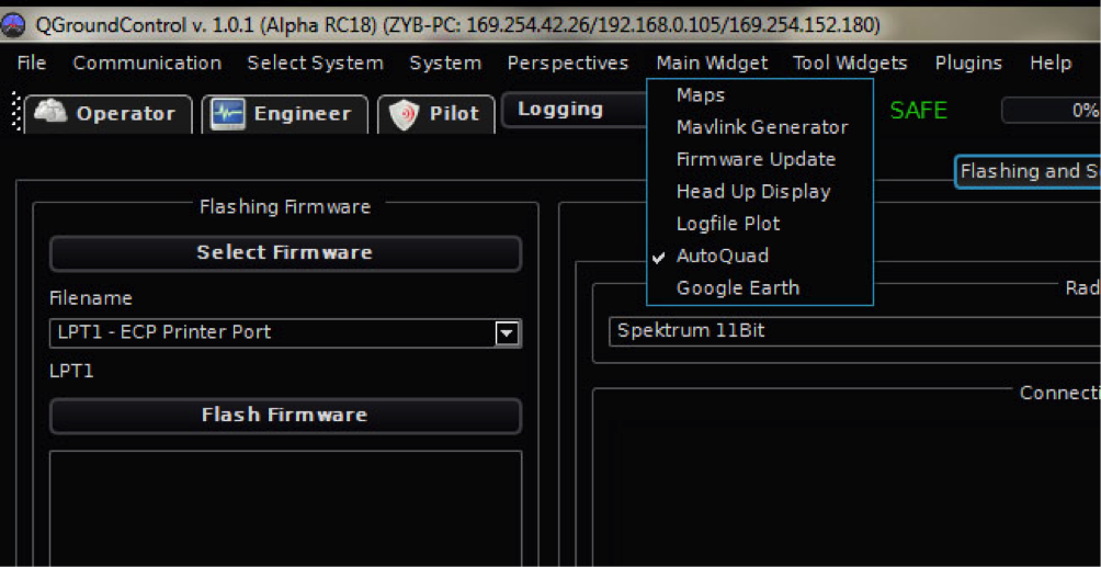
Connect the ESC32 using your FTDI interface to the computer and start QGCS. Make sure the AutoQuad widget is visible in the engineering tab. Click on Esc32 Settings.

컴퓨터에 여러분의 FTDI 인터페이스를 사용해서 ESC32를 연결하고 QGCS를 실행시킵니다. AutoQuad 위젯이 engineering tab에 보여야 하고 ESC32 설정을 클릭합니다.

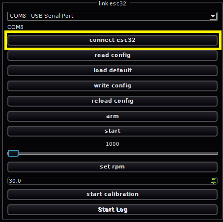
Proceed with connecting the esc32 by clicking on the ‘connect esc32’ button. That one!!, make sure you did NOT use any other connect button only that one.

'connect esc32' 버튼을 클릭해서 ESC32를 연결을 진행합니다. 여러분은 다른 버튼을 사용하지 말고 오직 'connect esc32' 버튼을 사용하세요.
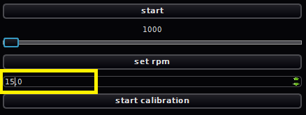
To set the maximum current to use in the calibrations you can adjust the default (20A) to any number. It will probably be good practice to start low and watch the first calibration. If you table, motor and room is still intact you can set a higher number.

정밀 조정에서 사용할 최대 전류를 설정하기 위해서 여러분은 디폴트(20A)를 다른 숫자로 조정할 수 있습니다. 이것은 아마도 낮게 시작하고 첫번째 정밀 조정을 볼 수 있는 좋은 예가 될 것입니다. 만일 여러분이 안정되면 모터와 공간은 변화 없이 더 큰 숫자를 설정할 수 있습니다.
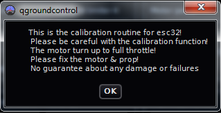
Final check and click on ‘start calibration’. The following warning will be displayed.

'start calibration'을 클릭합니다. 다음의 경고가 표시될 것입니다.

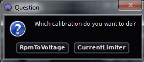
Next you can select the two calibrations. Select the one you need (or do both).

다음 여러분은 2가지 정밀 조정을 선택할 할 수 있습니다. 여러분이 필요한 하나를 선택하세요(혹은 둘다).

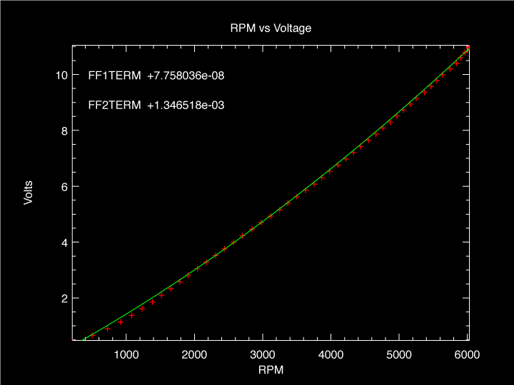
The calibration will now start and take some time. The calibration sequence will ramp up the duty cycle in several steps and measure rpm, current, duty cycle and voltage. It can produce output like this if you graph the data (next versions or if you use the linux version with plplot). In the current QGCS a comma separated file is generated in the QGCS directory that can be imported into a spreadsheet program.

정밀 조정은 지금 시작하고 시간이 소요됩니다. 정밀 조정 절차는 몇 개의 단계로 듀티 사이클을 올리고 rpm, 전류, 듀티 사이클 그리고 전압을 측정할 것입니다. 이것은 여러분이 데이터를 그래프로 그린다면 (다음 버젼 혹은 plplot의 리눅스 버젼을 사용한다면) 이와 같은 결과를 만들 것입니다. 현재의 QGCS에서 콤마로 분리된 파일이 QGCS 디렉토리에 생성되고 이는 스프레드시트 프로그램에서 읽어 들일 수 있습니다.


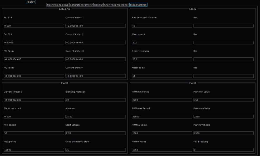
After the calibration the current limiter (1-5) or FF (1-2) data is displayed and entered in the Esc32 PID screen.

정밀 조정 후에 current limiter (1-5) 혹은 FF (1-2) 데이터는 보여지고 Esc32 PID 화면으로 들어갑니다.
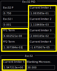
Now click on ‘write config’ to save them to the ESC32 memory.

이들은 ESC32 메모리에 저장하기 위해서 'write config'를 클릭합니다.
Final check. Click on disconnect esc32 and again on connect esc32 for a definitive check if the values have been stored to flash and can be retrieved by using connect esc32

'disconnect esc32' 버튼을 클릭합니다. 그리고 값이 제대로 플래시 메모리에 저장되었는지는 확인하기 위해서 다시 'connect esc32' 버튼을 클릭합니다.

You have to manually enter the calibration data in your other esc32’s.
다른 esc32에는 정밀조정한 데이터를 수동으로 입력해야 합니다.


Calibration via command line (Ubuntu)

When using the QGCS, the executables for calibration are in the software, but when using the commandline binaries on linux or OSx you need to compile them.

Prerequisites

  1. ESC32 source on the google code page
  2. eigen3 development library for your distro
  3. plplot development library for your distro

Install the required packages

sudo apt-get install subversion build-essential libplplot-dev libeigen3-dev

Add the current user to the dialout group to run esc32Cal as normal user

sudo usermod -a -G dialout $USER
After the next login esc32Cal can be run as normal user.

Checkout the latest ESC32 code

svn checkout http://esc32.googlecode.com/svn/trunk/ esc32

Edit Makefile (esc32/ground) to adapt Eigen3 library path

esc32Cal.o: esc32Cal.cc esc32.h
$(CC) -c $(ALL_CFLAGS) esc32Cal.cc -I/opt/local/include -I/usr/include/eigen3

Compile esc32Cal

make esc32Cal
Note: The warnings can be ignored!

Available Parameters

–cl Current Limiter calibration
–r2v Feed Forward calibration (RPM to Voltage)
-a amps Limits current during calibration
-p device USB to TTL converter port
-b baud Baud rate
-t file Telemetry output file

The device port (-p switch) must be set and depends on the used converter (“dmesg” can help to indetify the port). It’s important to limit the maximum current (-a switch) to match the drive combination (motor/propeller/voltage). A value to high can burn the motor or ESC! Ctrl+C can be used to terminate esc32Cal.

Current Limiter calibration

./esc32Cal --cl -p /dev/ttyUSB0 -a 15

At the end of the calibration the CLxTERM values are displayed:
#define DEFAULT_CL1TERM         +3.358974e-01
#define DEFAULT_CL2TERM         +1.124178e-03
#define DEFAULT_CL3TERM         +3.390607e-02
#define DEFAULT_CL4TERM         -3.829096e-05
#define DEFAULT_CL5TERM         +1.367444e+00

Feed Forward calibration

./esc32Cal --r2v -p /dev/ttyUSB0 -a 15

At the end of the calibration the FFxTERM values are displayed:
#define DEFAULT_FF1TERM         +8.008604e-08
#define DEFAULT_FF2TERM         +1.249541e-03

'Radio Control > ESC' 카테고리의 다른 글

ESC32 - config  (0) 2020.04.29
ESC32 V2 메뉴얼 - Configuration & Modes  (0) 2020.04.24
ESC32 V2 메뉴얼 - Firmware Flashing  (0) 2020.04.23
ESC32 V2 메뉴얼 - Connections & Wiring  (0) 2020.04.03
BitWizard ESC의 소개  (0) 2018.12.03
Posted by Nature & Life
Radio Control/ESC2020. 4. 29. 21:29

config.h

/*

    This file is part of AutoQuad ESC32.


    AutoQuad ESC32 is free software: you can redistribute it and/or modify

    it under the terms of the GNU General Public License as published by

    the Free Software Foundation, either version 3 of the License, or

    (at your option) any later version.


    AutoQuad ESC32 is distributed in the hope that it will be useful,

    but WITHOUT ANY WARRANTY; without even the implied warranty of

    MERCHANTABILITY or FITNESS FOR A PARTICULAR PURPOSE.  See the

    GNU General Public License for more details.

    You should have received a copy of the GNU General Public License

    along with AutoQuad ESC32.  If not, see <http://www.gnu.org/licenses/>.


    Copyright © 2011, 2012, 2013  Bill Nesbitt

*/


#ifndef _CONFIG_H

#define _CONFIG_H


#define DEFAULT_CONFIG_VERSION 2.01f

#define DEFAULT_STARTUP_MODE 0.0f

#define DEFAULT_BAUD_RATE 230400

#define DEFAULT_ESC_ID 0


#define DEFAULT_PTERM 0.25f

#define DEFAULT_PNFAC 10.0f

#define DEFAULT_ITERM 0.0006f

#define DEFAULT_INFAC 0.15f


#define DEFAULT_FF1TERM 0.0f

#define DEFAULT_FF2TERM 0.0f


#define DEFAULT_CL1TERM 0.0f

#define DEFAULT_CL2TERM 0.0f

#define DEFAULT_CL3TERM 0.0f

#define DEFAULT_CL4TERM 0.0f

#define DEFAULT_CL5TERM 0.0f


#define DEFAULT_THR1TERM 0.0f

#define DEFAULT_THR2TERM 1.0f


#define DEFAULT_SHUNT_RESISTANCE 0.5f     // milli Ohms

#define DEFAULT_MIN_PERIOD 50.0f     // us

#define DEFAULT_MAX_PERIOD 12000.0f    // us

#define DEFAULT_BLANKING_MICROS 30.0f     // us

#define DEFAULT_ADVANCE 10.0f     // electrical degrees

#define DEFAULT_START_VOLTAGE 1.1f     // voltage used to start motor

#define DEFAULT_START_ALIGN_TIME 600     // ms to align rotor in known position

#define DEFAULT_START_ALIGN_VOLTAGE 0.9f     // max voltage during align (around 0.8 * START_VOLTAGE)

#define DEFAULT_START_STEPS_NUM 0.0f     // steps without commutation

#define DEFAULT_START_STEPS_PERIOD 16000     // us betweet steps

#define DEFAULT_START_STEPS_ACCEL 0.0f     // us each following step will be shorter (acceleration)

#define DEFAULT_GOOD_DETECTS_START 75.0f     // after which will go into RUNNING mode

#define DEFAULT_BAD_DETECTS_DISARM 48.0f     // after which will go into DISARMED mode

#define DEFAULT_MAX_CURRENT 20.0f     // amps

#define DEFAULT_SWITCH_FREQ 20.0f     // output PWM frequency in KHz

#define DEFAULT_MOTOR_POLES 14.0f


#define DEFAULT_PWM_MIN_PERIOD 2200     // minimum valid period

#define DEFAULT_PWM_MAX_PERIOD 25000     // maximum valid period


#define DEFAULT_PWM_MIN_VALUE 750     // minimum to consider pulse a valid signal

#define DEFAULT_PWM_LO_VALUE 1000     // lowest running value

#define DEFAULT_PWM_HI_VALUE 1950     // highest running value

#define DEFAULT_PWM_MAX_VALUE 2250     // maximum to consider pulse a valid signal

#define DEFAULT_PWM_MIN_START 1100     // minimum value required to start


#define DEFAULT_PWM_LOWPASS 0.0f     // lowpass on PWM input values (0 = none, 10 = heavy, no upper limit)

#define DEFAULT_RPM_MEAS_LP 0.5f     // lowpass measured RPM values for closed loop control (0 = none, 0.99 = max, >=1 not allowed)


#define DEFAULT_PWM_RPM_SCALE 6500     // RPM equivalent of maximum PWM IN in CLOSED_LOOP mode


#define DEFAULT_FET_BRAKING 0


#define DEFAULT_SERVO_DUTY 16.0f     // %

#define DEFAULT_SERVO_P 0.05f

#define DEFAULT_SERVO_D 0.0f

#define DEFAULT_SERVO_MAX_RATE 1000.0f     // deg/s

#define DEFAULT_SERVO_SCALE 360.0f     // deg

#define DEFAULT_DIRECTION 1.0f     // 1 == forward, -1 == reverse


#define FLASH_PAGE_SIZE ((uint16_t)0x400)

#define FLASH_WRITE_ADDR (0x08000000 + (uint32_t)FLASH_PAGE_SIZE * 63)    // use the last KB for storage


enum configParameters {

    CONFIG_VERSION = 0,

    STARTUP_MODE,

    BAUD_RATE,

    PTERM,

    ITERM,

    FF1TERM,

    FF2TERM,

    CL1TERM,

    CL2TERM,

    CL3TERM,

    CL4TERM,

    CL5TERM,

    SHUNT_RESISTANCE,

    MIN_PERIOD,

    MAX_PERIOD,

    BLANKING_MICROS,

    ADVANCE,

    START_VOLTAGE,

    GOOD_DETECTS_START,

    BAD_DETECTS_DISARM,

    MAX_CURRENT,

    SWITCH_FREQ,

    MOTOR_POLES,

    PWM_MIN_PERIOD,

    PWM_MAX_PERIOD,

    PWM_MIN_VALUE,

    PWM_LO_VALUE,

    PWM_HI_VALUE,

    PWM_MAX_VALUE,

    PWM_MIN_START,

    PWM_RPM_SCALE,

    FET_BRAKING,

    PNFAC,

    INFAC,

    THR1TERM,

    THR2TERM,

    START_ALIGN_TIME,

    START_ALIGN_VOLTAGE,

    START_STEPS_NUM,

    START_STEPS_PERIOD,

    START_STEPS_ACCEL,

    PWM_LOWPASS,

    RPM_MEAS_LP,

    SERVO_DUTY,

    SERVO_P,

    SERVO_D,

    SERVO_MAX_RATE,

    SERVO_SCALE,

    ESC_ID,

    DIRECTION,

    CONFIG_NUM_PARAMS

};


extern float p[CONFIG_NUM_PARAMS];

extern const char *configParameterStrings[];

extern const char *configFormatStrings[];


extern void configInit(void);

extern int configSetParam(char *param, float value);

extern int configSetParamByID(int i, float value);

extern int configGetId(char *param);

extern float configGetParam(char *param);

extern void configLoadDefault(void);

extern void configReadFlash(void);

extern int configWriteFlash(void);


#endif


config.c

/*

    This file is part of AutoQuad ESC32.


    AutoQuad ESC32 is free software: you can redistribute it and/or modify

    it under the terms of the GNU General Public License as published by

    the Free Software Foundation, either version 3 of the License, or

    (at your option) any later version.


    AutoQuad ESC32 is distributed in the hope that it will be useful,

    but WITHOUT ANY WARRANTY; without even the implied warranty of

    MERCHANTABILITY or FITNESS FOR A PARTICULAR PURPOSE.  See the

    GNU General Public License for more details.

    You should have received a copy of the GNU General Public License

    along with AutoQuad ESC32.  If not, see <http://www.gnu.org/licenses/>.


    Copyright © 2011-2014  Bill Nesbitt

*/


#include "config.h"

#include "fet.h"

#include "pwm.h"

#include "adc.h"

#include "run.h"

#include "serial.h"

#include "can.h"

#include "stm32f10x_flash.h"

#include "stm32f10x_rcc.h"

#include <string.h>

#include <math.h>


float p[CONFIG_NUM_PARAMS];


const char *configParameterStrings[] = {

    "CONFIG_VERSION",

    "STARTUP_MODE",

    "BAUD_RATE",

    "PTERM",

    "ITERM",

    "FF1TERM",

    "FF2TERM",

    "CL1TERM",

    "CL2TERM",

    "CL3TERM",

    "CL4TERM",

    "CL5TERM",

    "SHUNT_RESISTANCE",

    "MIN_PERIOD",

    "MAX_PERIOD",

    "BLANKING_MICROS",

    "ADVANCE",

    "START_VOLTAGE",

    "GOOD_DETECTS_START",

    "BAD_DETECTS_DISARM",

    "MAX_CURRENT",

    "SWITCH_FREQ",

    "MOTOR_POLES",

    "PWM_MIN_PERIOD",

    "PWM_MAX_PERIOD",

    "PWM_MIN_VALUE",

    "PWM_LO_VALUE",

    "PWM_HI_VALUE",

    "PWM_MAX_VALUE",

    "PWM_MIN_START",

    "PWM_RPM_SCALE",

    "FET_BRAKING",

    "PNFAC",

    "INFAC",

    "THR1TERM",

    "THR2TERM",

    "START_ALIGN_TIME",

    "START_ALIGN_VOLTAGE",

    "START_STEPS_NUM",

    "START_STEPS_PERIOD",

    "START_STEPS_ACCEL",

    "PWM_LOWPASS",

    "RPM_MEAS_LP",

    "SERVO_DUTY",

    "SERVO_P",

    "SERVO_D",

    "SERVO_MAX_RATE",

    "SERVO_SCALE",

    "ESC_ID",

    "DIRECTION"

};


const char *configFormatStrings[] = {

    "%f",     // CONFIG_VERSION

    "%.0f",     // STARTUP_MODE

    "%.0f baud",    // BAUD_RATE

    "%.3f",     // PTERM

    "%.5f",     // ITERM

    "%+e",     // FF1TERM

    "%+e",     // FF2TERM

    "%+e",     // CL1TERM

    "%+e",     // CL2TERM

    "%+e",     // CL3TERM

    "%+e",     // CL4TERM

    "%+e",     // CL5TERM

    "%.3f mohms",   // SHUNT_RESISTANCE

    "%.0f us",     // MIN_PERIOD

    "%.0f us",     // MAX_PERIOD

    "%.0f us",     // BLANKING_MICROS

    "%.2f Degs",    // ADVANCE

    "%.2f Volts",   // START_VOLTAGE

    "%.0f",     // GOOD_DETECTS_START

    "%.0f",     // BAD_DETECTS_DISARM

    "%.1f Amps",    // MAX_CURRENT

    "%.1f KHz",     // SWITCH_FREQ

    "%.0f",     // MOTOR_POLES

    "%.0f us",     // PWM_MIN_PERIOD

    "%.0f us",     // PWM_MAX_PERIOD

    "%.0f us",     // PWM_MIN_VALUE

    "%.0f us",     // PWM_LO_VALUE

    "%.0f us",     // PWM_HI_VALUE

    "%.0f us",     // PWM_MAX_VALUE

    "%.0f us",     // PWM_MIN_START

    "%.0f RPM",     // PWM_RPM_SCALE

    "%.0f",     // FET_BRAKING

    "%.2f",     // PNFAC

    "%.2f",     // INFAC

    "%+e",     // THR1TERM

    "%+e",     // THR2TERM

    "%.0f ms",     // START_ALIGN_TIME

    "%.2f Volts",   // START_ALIGN_VOLTAGE

    "%.0f",     // START_STEPS_NUM

    "%.0f us",     // START_STEPS_PERIOD

    "%.0f us",     // START_STEPS_ACCEL

    "%2.2f",     // PWM_LOWPASS

    "%.3f",     // RPM_MEAS_LP

    "%.1f %%",     // SERVO_DUTY

    "%.3f",     // SERVO_P

    "%.3f",     // SERVO_D

    "%.1f deg/s",   // SERVO_MAX_RATE

    "%.1f deg",     // SERVO_SCALE

    "%.0f",     // ESC_ID

    "%.0f"     // DIRECTION

};


void configInit(void) {

    float ver;


    configLoadDefault();


    ver = *(float *)FLASH_WRITE_ADDR;


    if (isnan(ver))

configWriteFlash();

    else if (ver >= p[CONFIG_VERSION])

configReadFlash();

    else if (p[CONFIG_VERSION] > ver)

configWriteFlash();

}


// recalculate constants with bounds checking

void configRecalcConst(void) {

    adcSetConstants();

    fetSetConstants();

    runSetConstants();

    pwmSetConstants();

    serialSetConstants();

    canSetConstants();

}


int configSetParamByID(int i, float value) {

    int ret = 0;


    if (i >= 0 && i < CONFIG_NUM_PARAMS) {

p[i] = value;

configRecalcConst();


ret = 1;

    }


    return ret;

}


int configSetParam(char *param, float value) {

    int ret = 0;

    int i;


    for (i = 0; i < CONFIG_NUM_PARAMS; i++) {

if (!strncasecmp(configParameterStrings[i], param, strlen(configParameterStrings[i]))) {

    configSetParamByID(i, value);

    ret = 1;

    break;

}

    }


    return ret;

}


int configGetId(char *param) {

    int i;


    for (i = 0; i < CONFIG_NUM_PARAMS; i++)

if (!strncasecmp(configParameterStrings[i], param, 16))

    return i;


    return -1;

}


float configGetParam(char *param) {

    int i;


    i = configGetId(param);


    if (i >= 0)

return p[i];

    else

return __float32_nan;

}


void configLoadDefault(void) {

    p[CONFIG_VERSION] = DEFAULT_CONFIG_VERSION;

    p[STARTUP_MODE] = DEFAULT_STARTUP_MODE;

    p[BAUD_RATE] = DEFAULT_BAUD_RATE;

    p[PTERM] = DEFAULT_PTERM;

    p[ITERM] = DEFAULT_ITERM;

    p[FF1TERM] = DEFAULT_FF1TERM;

    p[FF2TERM] = DEFAULT_FF2TERM;

    p[CL1TERM] = DEFAULT_CL1TERM;

    p[CL2TERM] = DEFAULT_CL2TERM;

    p[CL3TERM] = DEFAULT_CL3TERM;

    p[CL4TERM] = DEFAULT_CL4TERM;

    p[CL5TERM] = DEFAULT_CL5TERM;

    p[SHUNT_RESISTANCE] = DEFAULT_SHUNT_RESISTANCE;

    p[MIN_PERIOD] = DEFAULT_MIN_PERIOD;

    p[MAX_PERIOD] = DEFAULT_MAX_PERIOD;

    p[BLANKING_MICROS] = DEFAULT_BLANKING_MICROS;

    p[ADVANCE] = DEFAULT_ADVANCE;

    p[START_VOLTAGE] = DEFAULT_START_VOLTAGE;

    p[GOOD_DETECTS_START] = DEFAULT_GOOD_DETECTS_START;

    p[BAD_DETECTS_DISARM] = DEFAULT_BAD_DETECTS_DISARM;

    p[MAX_CURRENT] = DEFAULT_MAX_CURRENT;

    p[SWITCH_FREQ] = DEFAULT_SWITCH_FREQ;

    p[MOTOR_POLES] = DEFAULT_MOTOR_POLES;

    p[PWM_MIN_PERIOD] = DEFAULT_PWM_MIN_PERIOD;

    p[PWM_MAX_PERIOD] = DEFAULT_PWM_MAX_PERIOD;

    p[PWM_MIN_VALUE] = DEFAULT_PWM_MIN_VALUE;

    p[PWM_LO_VALUE] = DEFAULT_PWM_LO_VALUE;

    p[PWM_HI_VALUE] = DEFAULT_PWM_HI_VALUE;

    p[PWM_MAX_VALUE] = DEFAULT_PWM_MAX_VALUE;

    p[PWM_MIN_START] = DEFAULT_PWM_MIN_START;

    p[PWM_RPM_SCALE] = DEFAULT_PWM_RPM_SCALE;

    p[FET_BRAKING] = DEFAULT_FET_BRAKING;

    p[PNFAC] = DEFAULT_PNFAC;

    p[INFAC] = DEFAULT_INFAC;

    p[THR1TERM] = DEFAULT_THR1TERM;

    p[THR2TERM] = DEFAULT_THR2TERM;

    p[START_ALIGN_TIME] = DEFAULT_START_ALIGN_TIME;

    p[START_ALIGN_VOLTAGE] = DEFAULT_START_ALIGN_VOLTAGE;

    p[START_STEPS_NUM] = DEFAULT_START_STEPS_NUM;

    p[START_STEPS_PERIOD] = DEFAULT_START_STEPS_PERIOD;

    p[START_STEPS_ACCEL] = DEFAULT_START_STEPS_ACCEL;

    p[PWM_LOWPASS] = DEFAULT_PWM_LOWPASS;

    p[RPM_MEAS_LP] = DEFAULT_RPM_MEAS_LP;

    p[SERVO_DUTY] = DEFAULT_SERVO_DUTY;

    p[SERVO_P] = DEFAULT_SERVO_P;

    p[SERVO_D] = DEFAULT_SERVO_D;

    p[SERVO_MAX_RATE] = DEFAULT_SERVO_MAX_RATE;

    p[SERVO_SCALE] = DEFAULT_SERVO_SCALE;

    p[ESC_ID] = DEFAULT_ESC_ID;

    p[DIRECTION] = DEFAULT_DIRECTION;


    configRecalcConst();

}


int configWriteFlash(void) {

    uint16_t prevReloadVal;

    FLASH_Status FLASHStatus;

    uint32_t address;

    int ret = 0;


    prevReloadVal = runIWDGInit(999);


    // Startup HSI clock

    RCC_HSICmd(ENABLE);

    while (RCC_GetFlagStatus(RCC_FLAG_HSIRDY) != SET)

runFeedIWDG();


    FLASH_Unlock();


    FLASH_ClearFlag(FLASH_FLAG_EOP | FLASH_FLAG_PGERR | FLASH_FLAG_WRPRTERR);


    if ((FLASHStatus = FLASH_ErasePage(FLASH_WRITE_ADDR)) == FLASH_COMPLETE) {

address = 0;

while (FLASHStatus == FLASH_COMPLETE && address < sizeof(p)) {

    if ((FLASHStatus = FLASH_ProgramWord(FLASH_WRITE_ADDR + address, *(uint32_t *)((char *)p + address))) != FLASH_COMPLETE)

break;


    address += 4;

}


ret = 1;

    }


    FLASH_Lock();


    runFeedIWDG();


    // Shutdown HSI clock

    RCC_HSICmd(DISABLE);

    while (RCC_GetFlagStatus(RCC_FLAG_HSIRDY) == SET)

;


    runIWDGInit(prevReloadVal);


    return ret;

}


void configReadFlash(void) {

    memcpy(p, (char *)FLASH_WRITE_ADDR, sizeof(p));


    configRecalcConst();

}


'Radio Control > ESC' 카테고리의 다른 글

ESC32 V2 메뉴얼 - Calibrations  (0) 2020.05.19
ESC32 V2 메뉴얼 - Configuration & Modes  (0) 2020.04.24
ESC32 V2 메뉴얼 - Firmware Flashing  (0) 2020.04.23
ESC32 V2 메뉴얼 - Connections & Wiring  (0) 2020.04.03
BitWizard ESC의 소개  (0) 2018.12.03
Posted by Nature & Life
Radio Control/ESC2020. 4. 24. 19:55

Connect ESC32 to AutoQuad Widget in QGroundControl

The Autoquad version of QGroundControl (QGC) has a widget included to alter settings of ESC32

To use a command line interface via Putty, please read Max Levine´s forum post.

Open QGC, and choose “AutoQuad” from the main widget menu:

QGroundControl(QGC)의 Autoquad 버전은 ESC32의 설정을 변경하기 위해 포함된 위젯를 갖고 있습니다.

Putty를 이용한 command line interface(CLI)를 사용하기 위해서는 Max Levine´s forum post를 읽어주세요.

QGC를 오픈하고 메인 위젯 메뉴에서 "AutoQuad"를 선택합니다:


Then go to the tab “ESC32 settings”

그리고 "ESC32 settings"으로 이동합니다.


On the left side of the screen you can see the “Link ESC32” Tab:

화면의 왼쪽에서 여러분은 "Link ESC32" 탭을 볼 수 있습니다.


Connect UART adapter to ESC32 and computer and choose the UART adapter you are using and click connect.

ESC32와 컴퓨터를 UART 어댑터로 연결하고 여러분이 사용하는 UART 어댑터를 선택하고 "connect"를 클릭합니다.

When you connect the ESC to UART, it will go into disarmed state (Red LED blinking). Try and click “arm” – the ESC green LED should light up. If there is a main power source and motor hooked to the ESC you can run the motor by clicking “Start” and the motor will run at low duty (Remove props always when working with your multirotor)

여러분이 ESC와 UART를 연결하였을 때 이는 disarmed 상태로 갈 것입니다(적색 LED 깜박임). "arm"을 클릭합니다 - ESC 녹색 LED가 켜져야만 합니다. 만일 메인 전원이 연결되어 있고 모터가 ESC에 연결되어 있다면 여러분은 "Start"를 클릭하는 것으로 모터를 작동시킬 수 있으며 모터는 낮은 duty로 회전할 것입니다(여러분의 multirotor와 작동시킬 때 항상 프롭을 제거하세요).

Now you can alter the parameters in ESC32, but

여러분은 지금 ESC32의 파라미터를 변경할 수 있습니다 그러나

Make sure you don’t change parameters unless you know how the different parameters affect operation. Certain parameter combinations can be fatal for the ESC and motor!

만일 여러분이 서로 다른 파라미터들이 동작에 어떻게 영향을 줄 지를 모른다면 파라미터를 변경하기 마세요. 어떤 파라미터들의 조합은 ESC와 모터에 치명적일 수 있습니다!

Refer to the User configurable parameters section for more information on what each parameter controls.

각각의 파라미터들의 무엇을 조절할 지에 대한 추가적인 정보를 위해서 User configurable parameters를 참조하세요.


When parameters have been altered, you can upload them to ESC32 by clicking “write config”

파라미터들이 변경되면 여러분은 "write config"를 클릭함으로써 ESC32에 이들 값을 업로드할 수 있습니다.


User configurable parameters:

Generally, no parameters will need to be changed for normal out of the box PWM operation.  However, there are various parameters that can be set. Each parameter is a single numerical value.

일반적으로 어떠한 파라미터들은 정상적으로 바로 사용할 수 있는 PWM 동작을 위해서 변경할 필요가 없습니다. 그러나 설정될 수 있는 다양한 파라미터들이 있습니다. 각 파라미터들은 독립적인 수치입니다.

Note that some combinations of parameters can cause damage to your motor or ESC.  It is recommended to leave most values at their default values unless you are sure of how they impact function and operation.

파라미터들의 어떤 조합은 여러분의 모터와 ESC의 손상을 야기할 수 있음을 기억하세요. 만일 여러분이 이들이 기능과 동작에 어떤 영향을 줄지 알지 못한다면 디폴트 값으로 대부분의 값을 남겨두는 것을 추천합니다.

If you want to use the ESC32 with other FCs like MultiWii, APM2 (or Open Pilot Revo w/ APM firmware) or DJI NAZA please read the comments concerning certain values.

만일 여러분이 ESC32를 MultiWii, APM2 (혹은 Open Pilot Revo w/ APM firmware) 혹은 DJI NAZA와 같은 다른 FC들과 함께 사용하기를 원한다면 관련된 어떤 값의 주석문을 읽어주세요.

ParameterFactory DefaultDescription
   
STATUP_MODE0This is the run mode that the ESC defaults to when first powered on.
0 == normal open loop operation,
1 == closed loop RPM mode,
2 == closed loop thrust mode (not yet implemented)
BAUD_RATE230400The UART baud rate.  Allowable range 9600 to 921600
   
PTERM0.5The P term for the RPM PI controller
ITERM0.0006The I term for the RPM PI controller
   
FF1TERM0.0Feed forward terms used for the RPM controller.  Closed loop RPM mode will not function until FF1 & FF2 terms have been set.
FF2TERM0.0These values should be calculated using the esc32Cal program with the –r2v option
   
CL1TERM0.0CL1TERM through CL5TERM are used by the virtual current limiter which will not function until they are set.
CL2TERM0.0If CL1TERM through CL5TERM is not set, a PI controller will be used for current limiting instead.
CL3TERM0.0CL1TERM through CL5TERM can be calculated using the esc32Cal program with the –cl option.
CL4TERM0.0 
CL5TERM0.0 
   
SHUNT_RESISTANCE0.5This parameter should NOT be changed from the factory default!!! (Value in milliohms)
   
MIN_PERIOD50

The minimum commutation period allowed in microseconds : 20KHz

MAX_PERIOD12000

The maximum commutation period allowed in microseconds : 83.3Hz 

   
BLANKING_MICROS30The number of microseconds to ignore back EMF after a commutation.
   
ADVANCE15The amount of timing advance in electrical degrees.  There are 60 electrical degrees in a commutation cycle.  This value can be set from 0 to 30 degrees.
START_VOLTAGE1.1The amount of voltage presented to the motor during startup. Allowable range is 0.1v to 3.0v
GOOD_DETECTS_START75Once started, the number of good, in order zero crossings needed to be detected before the motor is considered to be in the running state.
BAD_DETECTS_DISARM48The number of missed zero crossing detects allowed before the ESC considers the motor not to be running at which point will go into the disarmed state.
   
MAX_CURRENT20The maximum amount of current in amps that the ESC will allow.  Current is dynamically regulated.  Always set this value low and only increase it if you know what you are doing.
SWITCH_FREQ20The output PWM pulse frequency used to power the motor windings in KHz.  Valid range is from 4KHz to 64KHz.
MOTOR_POLS14The number of magnetic poles used in the motor’s construction.  This value only needs to be set correctly if you want to use the RPM closed loop mode.
   
PWM_MIN_PERIOD2200The minimum period in microseconds that the ESC will consider an input PWM waveform to be valid.  Default value represents approx 450Hz. For MultiWii and ArduCopter APM (or Open Pilot Revo w/ APM fw) this value needs to be changed to 2000!
PWM_MAX_PERIOD25000The maximum period in microseconds that the ESC will consider an input PWM waveform to be valid.  Default value represents approx 40Hz
   
PWM_MIN_VALUE750The minimum input PWM pulse length in microseconds which the ESC will consider to be valid. For DJI Naza this value has to be 900!
PWM_LO_VALUE1000The input PWM pulse length in microseconds for the lowest throttle setting. For ArduCopter APM (or Open Pilot Revo w/ APM fw) this value needs to be changed to 1035!
PWM_HI_VALUE1950The input PWM pulse length in microseconds for the highest throttle setting.
PWM_MAX_VALUE2250The maximum input PWM pulse length in microseconds which the ESC will consider to be valid.
PWM_MIN_START1100The input PWM pulse length in microseconds at which the motor will be started.  Once running, the throttle can be brought as low as PWM_MIN_VALUE as long as the motor does not stall.
   
PWM_RPM_SCALE6500The scale of the input PWM pulse length.  In closed loop RPM run mode, PWM_LO_VALUE will indicate 0 RPM and PWM_HI_VALUE will indicate this RPM. Closed loop modes only!
FET_BRAKING0Turns on regenerative braking in closed loop modes (experimental),  
0 == off,
1 == on. Closed Loop modes only!!

Closed loop calibration

The ESC32 offers a closed loop RPM mode and a Closed loop thrust mode (Experimental). It requires calibration of the specific motor and prop you will be using.

ESC32는 closed loop RPM mode와 closed loop thrust mode(실험적인)를 제공합니다. 이는 여러분이 사용하고자 하는 특별한 모터와 프롭의 정밀한 조정을 요구합니다.

The calibration sequence is at an early stage in QGC and can be run under Linux and OSX from a terminal.

컬리브레이션 절차는 QGC에 초기 단계에 있고 이는 Linux와 OSX 하에서 작동시킬 수 있습니다.

Closed loop calibration instructions

Please be very careful running a calibration!
Your motors will perform certain patterns up to full power. Make sure to run these tests only in a secured environment!
Only use it in closed rooms or boxes where propellors can fly off without hurting anyone or damaging anything!

컬리브레이션은 매우 주의하여 진행하세요!
여러분의 모터들은 최대 파워까지 어떤 패턴으로 동작할 것입니다. 안전한 환경에서만 이들 테스트들이 진행되는지 확인해야 합니다! 프로펠러가 누군가 혹은 어떤 것을 다치게 하는 것 없이 동작할 수 있는 닫힌 공간이나 박스에서만 이를 사용하세요!

Refer to forum.autoquad.org for more details on how to perform closed loop calibration of ESC32 under Linux, OSX or from within QGC.

'Radio Control > ESC' 카테고리의 다른 글

ESC32 V2 메뉴얼 - Calibrations  (0) 2020.05.19
ESC32 - config  (0) 2020.04.29
ESC32 V2 메뉴얼 - Firmware Flashing  (0) 2020.04.23
ESC32 V2 메뉴얼 - Connections & Wiring  (0) 2020.04.03
BitWizard ESC의 소개  (0) 2018.12.03
Posted by Nature & Life
Radio Control/ESC2020. 4. 23. 21:45

ESC32 V2 Flashing Quick Guide


Preparations:
Make sure you have a correctly compiled *.hex file at hand.
ESC32 needs to have the headers for the FTDI/USB adapter and boot jumper soldered – also don’t forget to set the solder jumper for the power supply (either 5V or Vb)
Connect your FTDI/USB adapter and the boot jumper, then power up the ESC. Read more…

여러분은 지금 올바로 컴파일된 *.hex 파일을 갖고 있는지 확인하세요.

ESC32는 FTDI/USB 어댑터를 위한 헤더와 남땜되어질 boot 점퍼를 갖고 있습니다 - 또한 전원을 위한 점퍼 설정하는 것을 잊지 마시기 바랍니다(5V 혹은 Vb 둘 중의 하나).

여러분의 FTDI/USB 어댑터와 boot 점퍼를 연결하고 ESC에 전원을 인가합니다.

In the AQ QGC select the “Engineer” tab with the AutoQuad Main Widget. Select “Flashing and Setup”

AQ QGC에서 AutoQuad 메인 위젯에서 "Engineer 탭을 선택하고 "Flashing and Setup"를 선택합니다.

In the “Flashing Firmware” part of the screen select your firmware you want to flash, select the appropriate COM port and click on “Flash Firmware”.

"Flashing Firmware"라는 화면에서 여러분이 플래시 하기 위한 펌웨어를 선택하고, 적당한 COM 포트를 지정하고 "Flash Firmware"를 클릭합니다.

In the message field above the Version number you should see the process of the upload, followed by a confirmation that flashing was performed successfully and the ESC will be rebooted.

버전 숫자 위의 메시지 란에서 여러분은 업로드의 과정을 보고 플래시가 성공적으로 실행되었는 지의 확인이 이어지고 ESC는 다시 부트될 것입니다.

To make sure everything went fine, disconnect the ESC from the power source and the FTDI/USB, close and reopen the QGC and connect your ESC again.
Open the “ESC32 Settings” tab, click on “Connect” and see if all values and settings are fine.

모든 것이 잘 되었는지를 확인하기 위해서 ESC에서 전원과 FTDI/USB 어댑터을 끊고, QGC를 닫았다 다시 실행시키고 ESC를 다시 연결합니다.

"ESC32 Settings" 탭을 열고 "Connect"를 클릭하고 모든 값들과 설정이 보이는지 확인합니다.

If you prefer a CLI (command line interface) via Putty or similar, follow the instructions in Max Levine´s forum post.

만일 여러분이 Putty 툴이나 유사한 것을 이용해서 CLI(command line interface)를 선호한다면 Max Levine´s forum post에 명령을 따라합니다.

You can now proceed with the ESC32 parameter configuration.

'Radio Control > ESC' 카테고리의 다른 글

ESC32 - config  (0) 2020.04.29
ESC32 V2 메뉴얼 - Configuration & Modes  (0) 2020.04.24
ESC32 V2 메뉴얼 - Connections & Wiring  (0) 2020.04.03
BitWizard ESC의 소개  (0) 2018.12.03
VESC 하드웨어(v4.x) 설정 메뉴얼  (0) 2018.01.24
Posted by Nature & Life
Radio Control/ESC2020. 4. 3. 21:34

Assembly of ESC32 V2

Autoquad ESC32v2 comes as a “SMT-preassembled” kit. This means the end user has add all connections themselves. We did this to keep cost low, and to allow you to configure ESC32 for your exact needs.

Autoquad ESC32v2는 SMT 소자로 조립된 키트입니다. 이는 최종 사용자가 모든 연결을 해야 함을 의미합니다. 저희는 낮은 비용을 유지하려고 이렇게 했고 여러분의 정확한 요구에 맞게 여러분이 ESC32를 설정하도록 하였습니다.


Kit contents:

  • ESC32 v2, SMT-preassembled and factory tested board.
  • 25cm servo wire with open end.
  • Input power wires
  • 330uF/35V low ESR capacitor, Panasonic EEUFC1V331B. Its ESR is 68 millohms. Its 50V counterpart is EEUFC1H331L, 60 millohms

Its up to you to configure the wiring so it fits your need and frame. We have shown one way to do it here:

결선하는 것은 여러분에게 달려있고 따라서 여러분의 요구에 부합할 것입니다. 저희는 여기서 이를 위한 한 가지 방법을 예시합니다:

Input Capacitor

The input capacitor is a critical component for ESC operation. The Supplied 330uF/35V capacitor in the kit is safe for “normal” use on up to 4S with continuous currents below 10A. Increase capacitance (add another in parallel or increase size) if:

입력 커패시터는 ESC 동작을 위해서 매우 중요한 소자입니다. 공급된 키트 내 330uF/35V 커패시터는 10A 이하에서 연속적인 전류를 공급하는 4S까지 "정상적인" 사용에서 안전합니다. 만일 다음의 경우에 커패시터를 증가시키세요 (또 다른 커패시터를 병렬로 추가하거나 크기를 키우세요): 

  • Running long wires from battery to ESC (more than 25cm)
  • Running high continous currents (remember cooling)
  • Using 5S (use 50V capacitor for 5S)

Input Capacitors should be Low ESR types always! (less than 100 milliohms)

입력 커패시터는 항상 낮은 ESR 타입을 사용해야 합니다(<100mΩ)

Design reference capacitors:

Panasonic EEUFC1V331B, 330uF/35V/68 millohms.
Panasonic EEUFC1H331L, 330uF/50v/60 milliohms (for 5S)

The Input capacitor(s) is soldered directly to the + and – pads on the ESC.

입력 커패시터는 ESC 상의 +와 - 패드에 곧바로 납땜합니다.

Observe the input capacitor polarity! The MINUS (-) mark on the capacitor must be connected to the ‘-‘ terminal of the ESC32. Failing this can blow up the capacitor and damage the ESC32!

입력 커패시터 극성에 주의합니다. 커패시터의 (-) 표시는 ESC32의 '-' 단자에 연결되어야 합니다. 만일 잘못 연결한다면 커패시터는 타버릴 수 있으며 ESC32를 손상시킬 수 있습니다.

Make sure the two capacitor legs are as short as possible and that they cannot be short-circuited to each other – consider using a small piece of shrink-wrap on each leg. Check for solder bridges and shorts across the capacitor legs.

두 개의 커패시터 다리는 가능한 한 짧아야 하고 서로 단락되지 않도록 확실히 해야 합니다. 각 다리에 작은 shrink-wrap 사용을 고려하세요.

Power Connection

There are multiple ways the main input wires can be connected. We leave it up to you to determine what works best for you. Make sure the there is no shorts across the main power input or the motor phases!

메인 입력 선들을 연결하는 여러가지 방법이 있습니다. 무엇이 여러분에게 가장 잘 동작할지는 여러분의 몫으로 남기겠습니다. 메인 파워 입력 혹은 모터 상에서 어떤 단락도 없는지 확실히 하세요!

UART Connection

The UART connector matches a standard FDTI style 6-pin connector. It is used for flashing firmware and connecting to GUI/CLI or running the ESC over the UART interface.

UART 커넥터는 표준 FTDI 스타일 6핀 커넥터를 사용합니다. 이는 펌웨어를 업로드하고 GUI/CLI를 연결하기 위해서 혹은 UART 인터페이스 연결로 ESC를 동작시키기 위해서 사용됩니다.

PWM Connection

Solder the PWM servo wire to the PWM pads or add header pins:

PWM 서보 선을 PWM 패드에 납땜하거나 헤더 핀을 추가합니다:


i2c Connection

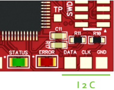
The ESC32 offers a I2C bus connection for future use. Support for MK I2C control will be released as soon as we had a chance to test it properly – talented people are working on this – a beta release is expected soon.

ESC32는 향후 사용을 위해서 I2C 버스를 제공합니다. MK I2C 제어를 위한 지원은 곧 출시될 것입니다. 저희는 이것이 적절하게 동작한다는 것을 확인하였습니다 - 숙련된 사람들은 이것을 이용하여 작업을 할 것입니다 - 베타 출시가 곧 될 것입니다.


CAN Connection

ESC32 can be fitted with an optional CAN transceiver (Texas Instruments SNHVD232) to provide CAN-bus control and bidirectional communication at up to 1mbit/s. New ESC32 have the CAN transceiver mounted. CAN is supported in the Firmware.

ESC32는 추가적인 CAN 송수신기(Texas Instruments SNHVD232)가 적용될 수 있고, 이는 CAN 버스 제어와 1mbit/s까지 양방향 통신을 지원합니다. 새로운 ESC32는 CAN 송수신기가 장착됩니다. CAN은 펌웨어에서 지원됩니다.

Cortex SWD Connection (J4)

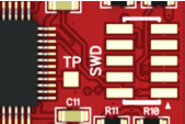
A standard 10-pin SMT cortex SWD connector (Samtec FTSH-105-01-F-DV) can be soldered to the board for realtime debugging of ESC32.

표준 10핀 SMT cortex SWD 커넥터(Samtec FTSH-105-01-F-DV)이 ESC32의 실시간 디버깅을 위해서 보드에 납땜시킬 수 있습니다.


Boot jumper

The boot jumper is used to place the STM32 bootloader in flash mode for uploading new firmware. Short these two pads during powerup to activate the Bootloader and place ESC32 in flash mode (Hint: you can use a pair of tweezers, if you are bit handy – you dont need to keep the pads shortened after the ESC has been powered up. However, if flashing is aborted with “..failed to get init ACK from device”-message keep the boot-pins shortened during the process until it´s completed and message “device rebootet” occurs)

부트 점퍼는 STM32 부트로더가 새로운 펌웨어의 업로드를 위해 플래시 모드에 놓기 위해서 사용됩니다. 부트로더를 활성화시키고 ESC32를 플래시 모드에 놓기 위해서 powerup 동안에 이들 두 패드를 단락시키세요.

Select Power for Logic Side

The ESC32 has two options for powering the logic side:

ESC32는 Logic 회로의 전원을 위해서 두 가지 옵션을 제공합니다:

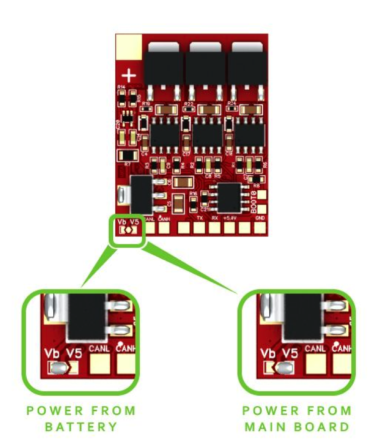
• On-board 3.3V LDO powered by main battery (Vb)
• 5V coming from UART or PWM interface (V5)

In most cases (especially when using LiPo batteries larger than 3S) it is recommended to power the ESC MCU with 5V from the PWM or UART interface – either from an external regulator or a UBEC hooked up to the servo rail on your FC or receiver.

대부분의 경우에 (특히 3S보다 큰 LiPo 배터리를 사용할 때) PWM 혹은 UART 인터페이스로부터 5V로 ESC MCU에 전원을 공급하는 것을 추천합니다 - 외부 regulator 혹은 여러분의 FC 혹은 수신기 상의 서보 전원에 연결된 UBEC도 가능합니다.

Selecting 5V, also means you can power up the logic side separately when flashing firmware or altering settings over 1-wire or UART interfaces, without the need to power up the motors.

5V를 선택한다는 것은, 펌웨어를 기록할 때 혹은 1-wire/UART 인터페이스 이용하여 설정을 변경할 때에 모터에 전원을 인가 할 필요 없이 Logic 회로를 분리하여 전원을 공급함을 의미합니다.

When using the 5V option to you must always DISCONNECT MAIN INPUT FIRST before disconnecting the 5V power to PWM or UART interface – disconnecting 5V while the main is still powered can damage the ESC.

5V 옵션을 사용할 때 PWM 혹은 UART 인터페이스에서 5V를 끊기 전에 여러분은 먼저 메인 입력을 항상 먼저 끊어야 합니다 - 메인이 여전히 전원이 공급되는 동안 5V를 끊는 것은 ESC를 손상시킬 수 있습니다.

To select the power source for MCU, locate the small solder jumper in the corner on the power side. It’s a simple 3-way solder jumper and works by connecting the middle pad to either the “Vb” or “V5” pads.

MCU의 전원을 선택하기 위해서 작은 납땜 점퍼를 사용합니다. 이는 간단한 3-way 납땜 점퍼로써 "Vb" 혹은 "V5", 둘 중 하나에 가운데 패드를 연결시키는 것으로서 작동합니다.


Final Checks before powering up

All ESC´s are tested in factory, before being released. But its a delicate piece of electronics running high currents, so you should Inspect your soldering carefully and make sure there is no shorts or solder splashes before powering up the first time. Measure with multimeter (if you have one) for shorts across the main power, PWM and the 3 motor phases.

모든 ESC는 출시되기 전에 공장에서 테스트합니다. 그러나 높은 전류에서 동작하는 전자기기이기 때문에 여러분의 납땜을 주의하여 육안으로 검사하고 처음 전원을 인가하기 전에 어떠한 단락이나 튄 납땜 조각이 있는 지를 확실히 하여야 합니다. 여러분이 갖고 있다면 멀티미터로 메인 전원과 PWM 그리고 3상 모터 상에 단락에 대하여 측정하세요.

First time you power up the ESC, we recommend to have the 5V option selected and hook it up to the AutoQuad widget in Qgroundcontrol or CLI via the UART interface without main power connected.

ESC를 처음 전원을 인가 할 때, 저희는 5V 옵션을 사용하고 메인 전원을 연결하지 않고 UART 인터페이스를 이용한 Qgroundcontrol 혹은 CLI로 AutoQuad 위젯을 연결하는 것을 추천합니다.

Alternatively you can hook ESC32 to a simple servo tester or receiver with 5V on the PWM interface. Don’t hook main power yet!

그밖에 여러분은 ESC32를 간단한 서보 테스터기 혹은 PWM 인터페이스 상에 5V를 갖는 수신기에 연결할 수 있습니다. 메인 전원은 아직 연결하지 마세요!

Note: Your servo tester needs to support >50Hz! Cheap/old units only support up to 40Hz.
When using your receiver, trim your throttle channel down on your transmitter to make the ESC32 initialize and arm.
주의: 여러분의 서보 테스터기는 50Hz 이상을 지원하는 것이 요구됩니다! 싸고 오래된 것은 단지 40Hz까지 지원합니다. 여러분의 수신기를 사용할 때 ESC32를 초기화하고 동작시키기 위해서 여러분의 송신기 상에 스로틀 채널을 아래로 미세조정하세요.

If the ESC gets 5V and a PWM pulse width of at least 750 microseconds, the green LED will light up showing you that the ESC is receiving a valid signal from your FC, RX or servo tester.

만일 ESC에 5V가 그리고 적어도 750us의 PWM 펄스폭이 공급된다면 초록색 LED가 켜질 것이고 이는 ESC가 여러분의 FC, RX 혹은 서보 테스터기로부터 유효한 신호를 수신하고 있음을 나타내는 것입니다.

You can now hook a power source to main power and check if the motor runs when you increase throttle. (Its a very good idea to use a small, limited power source like a 9V/500ma DC adapter to perform the first tests. This will secure nothing gets burned in case you have a short in your soldering somewhere. If you hook directly to a high current source (like a lipo battery) and there is a short, you can fry both ESC, battery and motor very quickly.

여러분은 지금 전원을 메인 파워로 연결시킬 수 있고 여러분이 스로틀을 증가시킬 때 모터가 회전하는 지를 확인하세요(처음 테스트를 실행하기 위해서 9V/500mA DC 어뎁터와 같은 작고 제한된 전원을 사용하는 것이 매우 좋은 생각입니다. 이는 경우에 따라서 여러분의 납땜이 어딘가에 단락되었을 때 타버리는 것을 방지할 수 있습니다. 만일 여러분이 높은 전류원(LiPo 배터리 같은)을 곧바로 연결하였고 단락이 있었다면 여러분은 ESC, 배터리 그리고 모터를 순식간에 태워버릴 수 있습니다. 

Inspect your soldering carefully and test the ESC on a limited supply before hooking it to a big battery.

여러분의 납땜을 주의롭게 육안으로 검사하고 큰 배터리에 연결하기 전에 제한된 전원으로 ESC를 테스트하세요.

ESC32 is now ready to run as a standard PWM ESC with very high motor refresh rate and a 1000-1950us throttle range with motor start at 1100uS. As such it can now be mounted to your favorite multi and flown right away.

ESC32는 매우 높은 모터 refresh rate로 표준 PWM ESC로서 동작합니다. 1100us에서 모터가 스타트하고 1000-1950us의 스로틀 범위를 갖습니다. 

Current and Cooling Considerations

How much current you can actually draw from ESC32, depends on how good they are cooled and where they are mounted.

ESC32로부터 실제로 얼마나 많은 전류를 당길 수 있는지는 여러분이 ESC32를 얼마나 잘 냉각시키고 어디에 부착하였는 지에 달려 있습니다.

Our general recommendation is to mount the ESC32 under or near the motors where they get cooled by the prop wash. Continous current drawings of 20A result in a slightly warm ESC. At under 10A per motor, cooling considerations are not needed. The gate-driven design means that the ESC´s wont warm up considerably when run at low currents.
The upper limit is probably upwards of 50A, but that will require extremely good cooling. The factory default for the current limiter in the firmware is 20A continuously. Going beyond that limit will require attention to proper cooling and temperature of the ESC.

저희들의 일반적인 권고는 프로펠라에 의해서 냉각시킬 수 있는 모터 근처에 ESC32를 부착하는 것입니다. 20A의 연속적인 전류는 ESC를 약간 발열나게 합니다. 모터 당 10A 이하에서 냉각 그 자체는 요구되지 않습니다. 게이트 구동 방식의 설계는 낮은 전류에서 동작시킬 때 ESC는 크게 발열되지 않음을 의미합니다. 상한은 아마도 50A 이상이 될 것입니다. 하지만 극도로 좋은 냉각시스템이 요구될 것입니다. 펌웨어에서 전류 제한을 위한 공장 디폴트는 연속적인 20A입니다. 이 한계를 넘어가는 것은 적절한 냉각과 ESC의 온도에 주의를 요구합니다.

Bear in mind that most “normal” setups under 3kg will stay well under 20A continuously per motor in normal flight conditions and hover (or something is very wrong with your choice of motors and props).

3kg 이하에서 가장 "정상적인" 설정은 정상적인 비행조건 그리고 호버링에서 모터 당 연속적인 20A 이하로 잘 유지될 것입니다.

Always test your individual setup and if you see signs of the ESC heating up it means you should add cooling. The better you cool your ESC´s, the more efficient they will also be so! In theory, they should continue to operate up to around 70-80 celsius, but they will age faster when run at high temps!

여러분의 개인적인 설정을 항상 테스트하세요 그리고 여러분이 ESC가 발열된다고 느낄 때 이것은 여러분이 냉각시스템을 추가해야 함을 의미합니다. 여러분이 ESC를 냉각을 잘 할수록 보다 효율적일 것입니다. 70-80℃까지 동작시키기도 하지만 높은 온도에서 작동시키는 것은 수명을 더 빨리 단축시킬 것입니다.

The best strategy keep ESC´s cool in a multirotor, is to place them in the wash from the rotors (Ideally right under the motors). In frames where that is not possible because of wiring considerations or if running high currents, heatsinks should be applied to the FETS on both sides. In general its not good practice to place ESC´s in tight places without any airflow, especially if running high currents!

멀티로터에서 ESC를 차게 유지하는 가장 좋은 방법은 로터의 바람에 위치시키는 것입니다(이상적으로 모터의 바로 밑에). 결선 때문에 프레임에서 불가능하거나 높은 전류에서 동작시킨다면 양쪽의 모든 FET 소자에 heatsink를 부착해야 합니다. 일반적으로 공기의 흐름이 없는, 특히 높은 전류에서 동작시키는 경우에는, 비좁은 곳에 ESC를 부착하는 것은 좋은 방법이 아닙니다.

LED Signals

red flashingno valid PWM signal (<750us or > 2100us)
prop strike
over current
greenready / armed
offrunning mode

Please be very careful running a calibration!
Your motors will perform certain patterns up to full power. Make sure to run these tests only in a secured environment!
Only use it in closed rooms or boxes where propellors can fly off without hurting anyone or damaging anything!


컬리브레이션을 할 때는 매우 주의하세요!

여러분의 모터는 최대 파워까지 어떤 패턴으로 실행될 것입니다. 안전한 환경에서만 이를 테스트 해야 합니다!

프로펠러가 누군가를 다치게 하거나 무언가를 손상시키거나 할 수 없는 닫힌 공간에서만 사용하세요!

Note: You can download these instructions as PDF file from our Download section.


Posted by Nature & Life
Radio Control/ESC2018. 12. 3. 19:47


다음의 Benjamin Vedder의 VESC에 기반을 두지만 보다 개선하였다는 BitWizard ESC(BESC)의 소개입니다.

http://bitwizard.nl/shop/ESC/BitWizard-ESC


The BitWizard ESC is a VESC compatible Brushless DC motor controller. It is based on the VESC by Benjamin Vedder, but has a few interesting differences!

BitWizard ESC는 VESC 호환 Brushless DC 모터 제어기입니다. 이는 Benjamin Vedder의 VESC에 기반을 두었지만 몇 가지 흥미있는 차이점을 갖고 있습니다.


Instead of the single integrated DRV8302 chip, the BESC uses separate gate drivers, opamps and a stepdown converter. This provides slightly better gate drive, as well as a possible upgrade path to larger voltages later on. 

한 개의 집적화된 DRV8302 칩 대신에, BESC는 개별의 게이트 드라이버와 opamp, stepdown 컨버터를 사용합니다. 이는 보다 우수한 게이트 구동 능력을 제공하며, 나중에 더 높은 전압으로의 업데이트 가능성을 제공합니다.


LCD I2C/SPI Interface, with 20x4 LCD


The current design has an SPI connector allowing connection of a "console display". This feature is working right now. Another option for expansion through that connector is an SD card to allow logging your session. This may help in debugging problems with the performance.

현재의 설계는 "console display"의 연결을 위한 SPI 커넥터를 갖습니다. 이 특성은 지금 동작 가능하며 이 커넥터를 통한 또 다른 확장 옵션은 여러분의 session을 기록하게 하는 SD 카드입니다. 이는 성능과 문제점을 디버깅 하는데 도움을 줄 수 있습니다.


BitWizard ESC


Just like VESC, the BESC has(VESC와 같은 점):


    • 60V theoretical MAX. In practise, some margin is required. Running on 14S LIPO is not recommended. 13S is tested works fine.

    • 50A continuous motor current. There is a temperature sensor on the power board that instructs the CPU to reduce the current if things heat up too much.

    • CAN bus connectivity. (currently untested).

    • Uart connectivity.

    • USB connectivity.

    • A connector with "servo pinout" for PWM input, PWM output.

    • Analog input for analog throttles.


Unlike the VESC the BESC has(VESC와 다른 점):


    • A boot button. This allows you to use DFU(dfuse) to reflash your BESC no matter how messed up the firmware has become. No need for an STLINK debugger.

Boot 버튼. 이는 펌웨어가 아무리 뒤죽박죽 될지라도 여러분이 여러분의 BESC를 재기록하기 위해서 DFU(dfuse)를 사용하는 것이 가능하게 합니다. STLINK 디버거에 대한 필요가 없습니다.

    • Separate gate drivers for the FETs.

FET들의 별도의 게이트 드라이버.

    • All unused IOs of the CPU broken out to a testpad.

모든 사용되지 않는 CPU의 IO 핀들은 tespad로 마련되어 있습니다.

    • A separate power board with all the FETs on one side. This allows you to cool the FETs with a heatsink against the PCB. (note: it is of no use to cool the plastic package of the FET. Cooling the PCB is what works.)

한 면에 모든 FET를 실장하는 분리된 power board. 이는 여러분이 heatsink로 FET를 식히는 것이 가능하게 합니다(note: FET의 플라스틱 패키지를 식히는 것이 필요 없다면, PCB를 식히는 것이 동작하는 것입니다).


Separate power board


    • A stepdown from the motor voltage to 12V. This 12V is used for the gate drivers.

모터 전압을 12V로 stepdown. 이 12V는 게이트 드라이버를 위해서 사용됩니다.

    • A stepdown from the 12V intermediate voltage to 5V. This 5V is used as the source for the 3.3V LDO for the CPU, but also provided on serveral connectors as a convenience to power for example a hall-sensor-throttle. On the VESC, they say you can use 1A, on the BESC the limit is slightly lower.

12V 중간 전압을 5V로 stepdown. 이 5V는 CPU의 3.3V LDO를 위한 소스이지만 예를 들어 홀센서 스로틀의 전력공급을 위한 편의를 위해서 몇 개의 커넥터를 제공됩니다. VESC 상에 그들은 여러분이 1A를 사용할 수 있다고 말하지만, BESC에서 한계는 약간 낮습니다.


During development we've had a lot of convenience of the separate power board. This allowed us to test with other FETs and stuff like that. When all is said and done, the IRFS7530 is a quite good fit. I could allow you to buy a version with cheaper FETs, but compared to the cost of the control module it doesn't make much sense to provide cheaper(smaller mosfet) power boards. But if you're interested anyway, get in touch.

개발하는 동안에 우리는 별개의 power board가 많이 편리하였습니다. 이는 우리가 다른 FET와 그와 같은 것과 테스트하는 것이 가능하였습니다. 모든 것을 종합적으로 고려해 보아 IRFS7530가 매우 적합하였습니다. 저는 여러분이 저렴한 FET 버전을 구매하도록 하였을 수 있습니다. 그러나 제어 모듈의 비용과 비교하여 이는 저렴한(작은 mosfet) power board를 제공하는 것이 큰 의미가 있지는 않습니다. 하지만 여러분이 어쨌든 관심있다면 연락주세요.


'Radio Control > ESC' 카테고리의 다른 글

ESC32 V2 메뉴얼 - Firmware Flashing  (0) 2020.04.23
ESC32 V2 메뉴얼 - Connections & Wiring  (0) 2020.04.03
VESC 하드웨어(v4.x) 설정 메뉴얼  (0) 2018.01.24
대표적인 상업용 VESC 구입처  (1) 2018.01.22
PX4ESC의 스펙  (0) 2015.12.08
Posted by Nature & Life
Radio Control/ESC2018. 1. 24. 15:40


이 메뉴얼은 Maytech에서 작성한 Maytech VESC Manual V1.1를 기반으로 작성된 한글 메뉴얼입니다. Maytech은 http://vedder.se/로부터 OBM에 따라서 VESC를 제작하였습니다. 비록 VESC 하드웨어와 펌웨어가 오프 소스이지만 Maytech은 전기적인 회로도나 PCB 배선 그리고 부품 버젼, 소스 코드를 변경하지 않았습니다. 그러나 Maytech도 공식적인 오픈 소스 하드웨어 & 펌웨어에 버그가 없다는 것을 보증할 수는 없습니다. VESC 제품을 사용 전에 사용자가 충분히 테스트 해야 합니다.


1. FEATURES    

◆ 하드웨어와 소프트웨어(펌웨어)는 오픈 소스입니다. MCU 리소스가 충분히 남았기 때문에 사용자는 나름데로 최적화 가능성이 무궁무진 합니다.

◆ STM32F4 32Bit ARM MCU.  

◆ DRV8302 MOSFET driver / buck converter / current shunt amplifier.  

◆ IRFS7530 MOEFETs.  

◆ DRV8302에 집적된 buck converter로부터 외장 전자장치를 위해서 5V 1.5A를 출력합니다. 

◆ Voltage: 8V – 60V (3s to 12s LiPo).  

◆ Current: 수 초간의 240A 혹은 온도와 PCB 주변의 공기 순환에 따라서 연속적으로 약 50A까지 공급합니다.

◆ Firmware based on ChibiOS real time OS.  

◆ PCB size: slightly less than 40mm x 60mm.  

◆ 모든 상에서 전류와 전압을 측정할 수 있습니다.

◆ Regenerative braking(회생 제동).

◆ DC motors are also supported.  

◆ Sensored or sensorless operation.  

◆ A GUI with lots of configuration parameters.  

◆ Adaptive PWM frequency to get as good ADC measurements as possible.  

◆ RPM-based phase advance (or timing/field weakening).  

◆ Good start‐up torque in the sensorless mode (and obviously in the sensored mode as well).  

◆ The motor is used as a tachometer, which is good for odometry on modified RC cars.  

◆ Duty‐cycle control(voltage control), speed control or current control. 

◆ Seamless 4‐quadrant operation.

◆ Interface to control the motor: PPM signal (RC servo), analog, UART, I2C, USB or CAN‐bus.      

◆ Wireless WII nunchuk (Nyko Kama) control through the I2C port. 전기 스케이트보드에서 편리합니다.    

◆ Consumed and regenerated amp‐hour and watt‐hour counting.     

◆ Optional PPM signal output. 예를 들어 Raspberry Pi나 안드로이드 디바이스로부터 RC 카를 제어할 때 유용합니다.

◆ USB 포트는 모뎀 프로파일을 사용합니다. 그래서 안드로이드 디바이스는 루팅(rooting)없이 모터 제어기에 연결할 수 있습니다. 서보 출력, 주행거리계(odometry)와 여분의 ADC 입력(센서를 위해서 사용될 수 있습니다)은 안드로이드(혹은 Raspberry Pi)로부터 제어되는 RC 카의 개조를 위해서 완벽합니다.

◆ Adjustable protection against:         

Low input voltage         

High input voltage         

High motor current         

High input current         

High regenerative braking current (separate limits for the motor and the input)         

Rapid duty cycle changes (ramping)         

High RPM (separate limits for each direction)     

◆ 전류 한계(current limit)에 도달했을 때 soft back‐off 전략이 모터가 동작하는 동안에 사용됩니다. 만일 전류가 너무 크다면 모터는 완전하게 커질 것입니다.

◆ RPM 한계(RPM limit) 또한 soft back‐off 전략을 갖습니다.     

◆ Commutation은 모터의 속도가 급격하게 변했을 때 조차도 완벽하게 동작합니다. 이는 이전 속도에 근거하여 시간 지연을 추가하는 방식 대신에 zero crossing 후에 자속(magnetic flux)이 적분된다는 사실 때문입니다.

◆ 제어기가 커진 동안 모터가 회전할 때, commutation과 회전 방향은 추적됩니다. 동일한 속도를 얻기 위해서 듀티 싸이클은 또한 계산됩니다. 

◆ 모든 하드웨어는 센서 없는 자속 기준 제어(Field‐Oriented Control; FOC)를 위해서 준비되었습니다. 소프트웨어를 작성하는 것이 남아있지만 많은 사용자는 FOC가 조금 정숙하게 동작한다는 것 이외에 낮은 인덕턴스 고속 모터를 대해서 많은 이득을 갖을 것인지에 대해서 확신하지는 못합니다.


2. SOME NOTES BEFORE USING VESC  

2.1 DC와 BLDC 모터 모두 VESC로 동작시킬 수 있습니다.

2.2 모터의 전류/전압이 VESC 제어 하에 있는지 확인하세요. VESC 전류/전압 범위는 8-60V 50A 연속적인 전류입니다.

2.3 VESC는 센서 있는 모터와 엔고더(encoder)가 장착된 모터 그리고 센서 없는 모터(sensorless motor)를 동작시킬 수 있습니다.  

2.4 속도 신호 형태를 체크하세요. VESC는 다음과 같은 신호를 수락합니다:

2.4.1 PPW: RC 산업계에서 PWM이라 부릅니다.

2.4.2 ADC: E‐bike 산업에서 Voltage Signal이라 부릅니다.

2.4.3 I2C: WII Remote Kama dongle.  

2.4.4 UART: 모바일 블루투스 어댑터. 게다가 속도 제어를 위해서 USB나 Can Bus를 사용할 수 있습니다.

2.5 전원이 배터리나 파워 어댑터로부터 공급되는지 확인하세요.

2.5.1 만일 배터리가 사용되면, 최대 방전 전류가 모터의 최대 전류보다 커야만 합니다.

2.5.2 만약 파워 어댑터를 사용한다면 우리는 다음을 조언합니다:

2.5.2.1 스위치 어댑터(switch adapter)가 아닌 리니어 어댑터(linear adapter)를 사용하세요.

2.5.2.2 브레이크를 끄세요 그렇지 않으며 'regenerative braking'가 발생할 때 VESC는 높은 전압을 출력하기 때문에 파워 어댑터가 손상될 수 있습니다.

2.6 스마트폰이나 컴퓨터에 앱이나 'BLDC Tool' 소프트웨어를 다운로드합니다. 이는 VESC 파라미터를 설정하기 위한 GUI입니다.

2.6.1 'BLDC Tool' 버젼은 VESC 하드웨어와 동일하지 확인하세요. 

2.6.2 Maytech은 윈도우 OS를 위한 'BLDC Tool'만을 제공합니다. 안드로이드나 리눅스 혹은 Mac OS에 대해서는 사용자가 컴파일하거나 다른 웹사이트에서 다운로드 해야만 합니다.

2.7 GUI screen shot과 파라미터들은 이들 플랫폼에서 얻어집니다:

MTVESC50A VESC: Firmware version 2.18; Hardware Version 4.12. 

BLDC TOOLS for Windows OS.

MTO6374 Motor KV 190,with Hall Sensor.

MTSKR1512 Wirelss remote controller: 1ms-2ms PPM.  

2.8 The VESC MTVESC50A 디폴트 셋팅:    

2.8.1 BLDC senslorless mode  

2.8.2 속도 신호는 1ms-2ms PPM입니다. 펄스폭이 1.5ms 이상일 때 모터는 단방향 회전을 시작합니다. 최대 속도는 2ms이고 브레이크 범위는 1-1.5ms입니다.


3. POWER WIRES CONNECTION:    

VESC는 곧바로 납땜을 하거나 고품질의 커넥터로 모터와 연결할 수 있습니다. 항상 새로운 커넥터를 사용하세요. 이 커넥터는 케이블과 주의하여 납땜해야 하며 heat shrink 튜브로 절연되어야 합니다. 밧테리팩 연결선의 최대 길이는 6인치(15.24cm) 이내여야 합니다.

◆ 배터리 연결선과 적당한 커넥터를 납땜합니다.

◆ 모든 납땜한 커넥터들을 heat shrink 튜브로 절연합니다.

◆ 모터 연결선에 VESC를 연결합니다.

◆ 제어기 빨강 그리고 검정 연결선을 배터리팩 빨강 그리고 검정 연결선에 각각 연결합니다.

Note : 만약 배터리 전압이 30V보다 크면 VESC가 배터리에 연결될 때 스파크가 생길 것입니다. 그래서 XT60/XT90 anti‐spark 커넥터가 추천됩니다.


4. HOW TO USE A NEW VESC?

MTVESC50A VESC 디폴트 셋팅은 대부분의 BLDC 모터가 동작하게 합니다. 안전을 고려해서 우선 파라미터를 확인하고 모터를 auto‐detect를 하기 위해 PC에 VESC를 연결하세요.

4.1 모터와 배터리를 VESC에 연결합니다. 모터는 부하가 걸려있지 않아야 합니다. VESC를 빨간등이 커졌을 때 USB 케이블로 PC와 연결합니다.

4.2 만약 VESC를 PC와 처음 연결한다면, 윈도우는 새로운 하드웨어를 발견했다고 알림을 줄 것입니다. 그리고 나서 윈도우는 드라이버를 자동적으로 설치할 것입니다. 만일 윈도우가 이전에 드라이버를 설치한 적이 있다면 다시는 이 드라이버를 설치하지 않을 것입니다.

4.3 새롭게 추가된 COM 포트는 Window Device Manager에서 발견될 것입니다. 'COMX'로 보여질 수 있고 'X'는 서로 다른 숫자가 될 것입니다. 

4.4 BLDC Tool을 기동하고 COMX를 선택하고 나서 "connect"를 클릭합니다. 접속이 성공하면 이는 우측하단 코너에 녹색을 보일 것입니다.

    그림 4.4 

4.5 'Configuration >> Motor'를 선택하고 'Read Configuration'을 클릭합니다. 이것은 VESC 셋팅을 읽어 올 것입니다. 파라미터가 아래 그림과 동일한 지를 확인합니다. 만약 동일하지 않으면 파라미터를 수정하고 나서 새로운 파라미터를 VESC 보드에 업로드 하기 위해 'Write Configuration'을 클릭합니다.

그림 4.5 

만약 설정 정보를 XML(eXtensible Markup Language) 포맷의 파일로 갖고 있다면 위 그림에서 우측 하단의 'Load XML'을 클릭하여 읽어 올 수 있습니다. 게다가 설정한 정보를 다시 XML 포맷의 파일로 저장하기를 원한다면 마찬가지로 'Save XML'을 클릭하여 저장할 수 있습니다.

4.6 'Motor Configuration >> BLDC'를 선택하고 'Read Configuration'을 클릭합니다. 이것은 VESC 셋팅을 읽어 올 것입니다. "Motor Type"이 BLDC인지 확인합니다. 그리고 나서 'Start detection'을 클릭합니다. 모터는 갑자기 3초간 회전할 것입니다. 많은 파라미터들이 모터가 정지한 후에 감지될 것입니다. 그리고 나서 이들 파라미터들을 적용하기 위해서 "Apply" 버튼을 클릭합니다. 만약 모터가 회전하지 않는다면, 이것은 VESC와 모터 연결에 문제가 있거나 혹은 디폴트 셋팅이 그 모터에 대해서 적당하지 않을 수 있습니다. 이 경우에 VESC와 모터의 연결을 확인하거나 혹은 수작업으로 'start‐up current'와 'minimum rotate speed'를 조정하세요. 모터 감지가 올바로 끝난 후에 파라미터들을 업로드 하기 위해서 'Write Configuration'을 클릭합니다.

Picture 4.6 

4.7 'App Configuration >> General'을 선택하고 'Read Configuration'을 클릭합니다. 이것은 VESC 셋팅을 읽어 올 것입니다. 파라미터들이 아래 그림과 동일한지 확인합니다. 만일 같지 않다면 파라미터를 수정하세요, 그리고 나서 새로운 파라미터들을 업로드 하기 위해서 'Write Configuration'을 클릭합니다. 만약 "APP to use"가 수정되었다면 VESC가 재부팅한 후에 적용될 것입니다.

Picture 4.7 

4.8 'App Configuration >> PPM'을 선택하고 'Read Configuration'을 클릭합니다. 만일 아래와 같지 않다면 파라미터들을 수정하세요. 그리고 나서 새로운 파라미터들을 업로드 하기 위해서 'Write Configuration'을 클릭합니다.

Picture 4.8 

4.9 서보 신호 케이블을 수신기에 연결하고 원격 조종기를 켭니다. 'Display'를 체크하세요. VESC가 원격 신호를 수신하는 것을 볼 수 있습니다.

Picture 4.9 

4.10 원격 조이스틱을 위로 미세요, 그러면 모터가 회전합니다. 조이스틱을 가장 낮은 위치로 당기세요, 그러면 모터가 브레이크 걸립니다. 이 순간이 VESC와 관련 장비들이 모두 괜찮은지 확인시켜주는 것입니다. 여러분은 다른 파라미터들을 조정하기 위해서 계속할 수 있습니다.      


5. ADJUST VESC PARAMETERS     

5.1 Motor Configuration  

5.1.1 Motor  

Picture 5.1.1 

5.1.1.1 Motor Type: BLDC/DC/FOC  

BLDC: Brushless Direct Current motor; PWM으로 속도를 조절합니다.

DC: Direct Current Motor; PWM으로 속도를 조절합니다.

FOC: Field‐Oriented Control은 vector 제어라고도 불리며 아래 허브 모터(hub motor)에 적당합니다.

5.1.1.2 Current Limits:  

Current Limits: 전류가 이 한계를 초과할 때 "Error"가 발생하고 빨간등이 깜박거립니다. VESC는 신호를 출력하는 것을 멈출 것입니다. '-'의 표현은 음으로 역방향을 의미합니다. 

5.1.1.3 RPM Limits (BLDC Only) PWM:  

Limit ERPM with negative torque: power generation mode가 높은 RPM에서 활성화될 것입니다.

Note: ERPM(Electrical RPM) = RPM*Pole/2 

5.1.1.4 Temperature:

만약 모터의 정확한 온도를 얻기를 원한다면 모터에 NTC(Negative Temperature Coefficient) 저항을 추가하세요. 홀센서 케이블로 VESC와 모터를 연결하세요.

5.1.1.5 Voltage Limits: 

전압의 한계값. 배터리와 VESC를 보호하기 위해서 배터리의 전압 한계를 설정하세요.

5.1.1.6 Other Limits: 

BLDC PWM 모드에서 Duty Ratio limits. 이것은 RPM.2의 최소 및 최대값을 제한할 수 있습니다.

5.1.2 BLDC

Picture 5.1.2 

5.1.2.1 Sensor Mode: Sensorless / Sensored /Hybrid  

Sensor mode로 start-up하고 어떤 RPM에서 sensorless mode로 전환하는데, 이를 Hybrid mode라 부릅니다. Sensor & Sensorless mode로부터 신호의 피드백에 따라 VESC는 commutation 시간을 측정합니다.

5.1.2.2 Sensorless:

Note: ERPM. BR ERPM은 이상적인 최대 Electrical RPM입니다.

Note: Phase advance at BR ERPM은 이상적인 최대 ERPM에서 phase advance입니다.

5.1.2.3 Sensorless Commutation Mode: Integrate/Delay

Integrate: Integrator Limit / Int Limit Min ERPM / BEMF Coupling 파라미터들은 "Detect Parameters" 메뉴로 자동적으로 채워질 것입니다. 'Start detection' 그리고 'Apply' 버튼을 클릭합니다. 파라미터들은 감지될 것입니다.

5.1.2.4 Hall Sensors:

테이블의 파라미터는 "Detect Parameters" 메뉴로 자동적으로 채워질 것입니다.

5.1.2.5 Detect Parameters:

파라미터를 감지하는 것은 새로운 모터를 사용할 때 매우 중요합니다. 배터리 그리고 VESC, 모터가 연결되었을 때 'Start Detect' 버튼을 클릭합니다. 모터는 감지되기 위해서 3초 동안 회전할 것입니다. Integrator limit / Int Limit Min ERPM / BEMF Coupling 파라미터들은 감지 후에 자동적으로 얻어질 것입니다. 만약에 홀센서(hall sensor)가 연결되었다면 홀센서 테이블의 파라미터도 감지될 것입니다.

Note: 'Start Detect'가 시작할 때 주의하세요.

Note: 만약에 모터가 'Start Detect'으로 동작하지 않는다면, 연결을 확인하세요. 필요하다면 Current / Min ERPM / Low duty를 조정하세요.

Note: 감지 후에 파라미터를 저장하기 위해서 'Apply' 버튼를 클릭하세요. VESC로 파라미터들을 업로드 하기 위해서 'Write configuration'를 클릭합니다.

Note: Sensored 혹은 Hybrid mode일 때 홀센서 테이블은 비록 자동으로 감지될지라도 홀센서가 설치된 위치는 차이가 존재합니다. 우리는 가장 낮은 전류로 그 조합을 설정하는데 수작업으로 phase sequence를 맞추기를 제안합니다.

5.1.3 FOC 

FOC(Field Oriented Control)는 모터가 좀 더 부드럽고 잡음이 적으며 전력을 많이 아끼도록 합니다. 그러나 모든 모터가 FOC를 지원하지는 않습니다. 모터 공급자에게 이를 확인하시기 바랍니다. FOC 제어 알고리즘은 전문적인 지식과 용어를 포함합니다. 설정 전에 먼저 살펴보시기 바랍니다. 우선 모터 파라미터를 감지하고 FOC 사용을 원한다면 λ, R, L, CC(TC, Kp, Ki)를 감지하세요. 홀센서 테이블은 홀 혹은 엔코더(encoder)가 사용될 때에는 또한 반드시 감지되어야 합니다:

Picture 5.1.3 

5.1.3.1 I / Duty / RPM이 채워졌을 때 'Measure λ' 버튼을 클릭하세요.

Picture 5.1.3.1‐1 

'λ'가 감지된 후에 'Apply'를 클릭합니다. 이것은 'Measure R and L'과 'Motor Parameters'안을 채울 것입니다.

Picture 5.1.3.1‐2

Picture 5.1.3.1‐3 

5.1.3.2 'λ'가 채워진 후에 'Measure R and L' 버튼을 클릭합니다. R & L 파라미터가 감지될 것입니다. 그리고 나서 'Apply'를 클릭합니다. 이것은 'Motor Parameters'안을 자동적으로 채울 것입니다.


Picture 5.1.3.2‐1

Picture 5.1.3.2‐2 

5.1.3.3 'Cale CC'를 클릭합니다 그러면 TC / Kp / Ki이 감지될 것입니다. 그리고 나서 'Apply'를 클릭합니다.

Picture 5.1.3.3   

5.1.3.4 General

Current Control: 전류 제어 모드(current control mode) 하에서 P/I 값.

Encoder: 엔코더(Encoder) 파라미터들.

Sensorless ERPM: Sensorless mode는 ERPM이 여러분이 설정한 값보다 클 때 활성화될 것입니다.     

5.1.3.5 General(Cont): General(Cont) Speed Counter setting.

F_SW and Dtc: 샘플링 주파수 그리고 deadband time.

Speed track: 속도 추적의 P/I 값.

Duty downramp: Duty downramp의 P/I 값.

Open RPM: Open-loop control은 ERPM이 여러분이 설정한 값보다 클 때 활성화됩니다.

Motor Parameters (for Sensorless and Hall Operation) setting, 5.1.3.1‐5.1.3.3을 참조하세요.

5.1.3.6 Sensorless Startup and Low Speed:

Open Loop: hysteresis and time

D Current Injection: d-축은 고정자에 DC 성분축이며 회전자 자계와 같은 방향입니다. 전류 주입은 회전자 위치를 감지하는데 용이하게 합니다. 

5.1.4 Advance 

5.1.4.1 PWM mode (DC and BLDC only)  

PWM 모드와 동기 제어(Synchronous control)는 Bipolar 제어보다 좀 더 안정적이지만 응답이 느립니다. 비동기(Nonsynchronous) 모드는 추천되지 않습니다.

5.1.4.2 Current control  

5.1.4.3 Backoff and ramping (DC and BLDC only) : Backoff and ramping parameters  

5.1.4.4 Speed Control   

5.1.4.5 Position Control  

5.1.4.6 Misc  

5.1.4.7 Hall/encoder Port mode

Picture 5.1.4

5.1.5 Description: 사용자는 여기에 메모할 수 있습니다.


Picture 5.1.5 

5.2 App Configuration: 'App Configuration' 입력 방법.

Picture 5.2 

5.2.1 General  

"App to use"는 VESC에서 중요한 파라미터입니다.

Picture 5.2.1  

입력 신호 소스를 선택합니다. 그러면 여러분은 대응하는 그 신호로 VESC를 제어할 수 있습니다(2.4를 참조하세요). 그리고 나서 'Write Configuration'을 클릭합니다. 이것은 VESC가 다시 시작한 후에 동작할 것입니다.

5.2.2 PPM: RC 모델 수신기 신호이며 PWM 신호인데 서보 케이블로 신호 입력을 제어합니다.

Picture 5.2.2‐1 

Picture 5.2.2‐2

5.2.2.1 Control Mode: 

Duty cycle / Duty cycle no reverse: 속도 제어

Current / Current no reverse / Current no reverse with Brake: 출력 전류를 제어하고 토크 제어와 유사한 효과를 갖습니다.

PID Speed control / PID Speed control no reverse: 이것은 속도가 변할 때 PID 파라미터로 제어합니다. PID 파라미터는 'Motor Configuration >> Speed Control'로 조정될 수 있습니다.

5.2.2.2 Setting: 

PID max ERPM: 'PID speed control / PID speed control no reverse'에 최대 ERPM입니다.

Deadband: 이것은 수신기 PPM의 "ms" 단위의 dead zone을 의미합니다. 여러분이 Maytech 원격 조종기를 사용한다면 0.2ms로 설정하세요.

Minimum Pulsewidth (ms): 가장 낮은 속도에서 PPM 신호의 펄스폭입니다. 여러분이 Maytech 원격 조종기를 사용한다면 1.5ms로 설정하세요.

Maximum Pulsewidth (ms): 가장 높은 속도에서 PPM 신호의 펄스폭입니다. 여러분이 Maytech 원격 조종기를 사용한다면 디폴트 셋팅(2.0ms)을 유지하세요.


User Median Filter: 이 필터는 PPM 신호의 간섭(interference)을 제거할 수 있습니다.

Safe Start: 갑작스러운 start-up으로 손상을 방지합니다.

5.2.2.3 Soft RPM limit (current mode only): 고속의 무부하 속도로부터 손상을 방지하기 위함입니다.

5.2.2.4 Multiple ESCs over Can: Can 버스로 연결되어 동작하는 여러 개의 ESC가 있을 때 토크를 같게 유지하기 위함입니다.

5.2.2.5 Display: PPM 신호의 듀티를 보여주기 위함입니다.

5.2.3 ADC: 전압 신호와 제어 신호는 P3 포트의 ADC 그리고 ADC2의 입력입니다. 이 ADC와 ADC2는 아날로그 신호 혹은 스위치 신호를 입력으로 받을 수 있습니다.

Picture 5.2.3‐1 

Picture 5.2.3‐2 

5.2.3.1 Control Mode:   

Current / Current center / Current Button/ Current no rev center / Current no rev button / Current no rev  

ADC2: ADC 혹은 ADC2에 아날로그 전압을 입력하는 것은 전류 출력의 크기와 방향을 제어할 수 있습니다. 이것은 토크 제어에 의해서 발생된 효과처럼 보입니다.

Duty cycle / Duty cycle center / Duty cycle button: ADC 혹은 ADC2에 아날로그 전압을 입력하는 것은 속도의 값과 방향을 제어할 수 있습니다.

5.2.3.2 Setting:           

Update Rate: ADC(transition of digital and analog) 샘플링 주파수.

DeadBand: 이것은 전압의 dead zone을 의미합니다. 간섭(interference)을 피하기 위해서 전압 변화 범위가 deadband 이상일 때 VESC에 의해서 오직 인식될 수 있습니다.

Minimum Voltage / Maximum Voltage: 입력 전압 신호의 최소 혹은 최대값을 의미합니다.

5.2.3.3 Button:

Current Button / Current no rev button / Duty cycle button mode에서 "Button"의 설명:  

쿠르즈(cruise) 제어 버튼은 전류 제어가 사용될 때 눌러진 동안 현재 속도를 유지할 것입니다. 그리고 어떠한 스로틀(throttle)도 받지 않습니다. 리버스(reverse) 버튼은 대응하는 제어 모드 중 하나가 사용될 때 스로틀을 거꾸로 하기 위해서 사용됩니다.

단지 'ADC app'만 사용될 때 TX 핀이 쿠르즈 제어 버튼으로 사용되고 RX 핀이 리버스 버튼으로 사용됩니다. 'ADC와 UART app'가 동시에 사용되면 서보 입력이 버튼으로써 사용될 것입니다. 이 경우에 이것은 버튼과 함께 제어 모드가 선택될 때 리버스 버튼으로써 사용될 것입니다. 그렇지 않으면 쿠르즈 제어 버튼으로써 사용될 것입니다.

5.2.3.4 Soft RPM limit (current mode only): 고속의 무부하 속도로부터 손상을 방지하기 위함입니다.  

5.2.3.5 Multiple ESCs over Can: Can 버스로 연결되어 동작하는 여러 개의 ESC가 있을 때 토크를 같게 유지하기 위함입니다.

5.2.3.6 Setting: UART Port - Baud rate.


Picture 5.2.3.6

5.2.4 Numchuk: WII Numchuk ‐ 원격 조종기의 파라미터.

Picture 5.2.4 

5.2.5 NRF: 블루투스(Bluetooth) 수신기의 파라미터.

Picture 5.2.5

5.2.6 GUI control

Picture 5.2.6

5.2.6.1 Contorl

'App Configuration'에서 우선 PPM, ADC 그리고 Numchuk에 'Disabled'를 설정하세요. 그리고 나서 인터페이스는 동작할 것입니다.

Duty 값을 설정합니다. 'Duty'를 클릭하세요 그러면 값이 저장됩니다. 모터는 여러분이 설정한 속도로 회전할 것입니다.

RPM 값을 설정합니다. 'RPM' 값을 클릭합니다. 그러면 값이 저장됩니다. 모터는 여러분이 설정한 RPM 값으로 회전할 것입니다.

전류값을 설정하세요. 'Current'를 클릭하세요 그러면 값이 저장됩니다. 모터는 여러분이 설정한 전류값으로 회전할 것입니다. 

Brake 값을 설정하세요. 'Brake'를 클릭하세요 그러면 값이 저장됩니다. 모터는 회전하는 동안에 여러분이 'Brake'를 클릭할 때 멈추게 될 것입니다.

위치값을 설정하세요. 'Position'을 클릭하세요 그러면 값이 저장됩니다. 모터는 여러분이 설정한 위치값으로 회전할 것입니다.

Note 1: 속도 혹은 전류는 'Motor Configuration'에 최대값을 초과할 수 없습니다.

Note 2: 만약 어떤 기능이 활성화되었다면, 모터는 다음 순서가 수신될 때까지 회전할 것입니다. 'Release Motor'을 클릭합니다 그러면 모터는 멈춥니다.

5.2.6.2 Plot and Sample

이 기능은 아직 테스트되지 않았고 가까운 미래에 가능할 것입니다.


'Radio Control > ESC' 카테고리의 다른 글

ESC32 V2 메뉴얼 - Connections & Wiring  (0) 2020.04.03
BitWizard ESC의 소개  (0) 2018.12.03
대표적인 상업용 VESC 구입처  (1) 2018.01.22
PX4ESC의 스펙  (0) 2015.12.08
ESC32의 스펙  (0) 2015.12.04
Posted by Nature & Life
Radio Control/ESC2018. 1. 22. 14:51


VESC 프로젝트를 기반으로 한 상업적 VESC와 구입처입니다. 대표적으로 제조사를 기준으로 하여 MayTech VESC, DIY ELECTRIC VESC(TORQUE ESC) 그리고 TRAMPA VESC 등이 있습니다. 상업용 제품은 MayTech VESC와 같이 출고시 펌웨어 업그레이드가 불가능할 수도 있습니다.


VESC Open Source Project인 VESC 소프트웨어와 호환되는 TORQUE ESC($99.99)


VESC BLDC는 가장 최근의 강력한 오프 소스 ESC이며 전기 스케이트보드(Electric Skateboard) 모터에 전력을 공급합니다. 이 ESC는 많은 사용자 지정 옵션을 수렴하여 만들어졌습니다. VESC를 사용하여 여러분은 완전한 정지 상태에서 센서 없는(sensorless) 모터를 출발할 수 있습니다.


v4.12 Hardware (Latest)

v2.18 Firmware (Latest)


VESC BLDC 오픈 소스 전기 스케이트보드 ESC VESC는 오픈 소스이며, Benjamin Vedder에 의해서 다양하게 변경이 가능한 전자 속도 제어기입니다. 여러분의 DIY 전기 스케이트보드 제작에 있어서 환상적으로 동작합니다. VESC는 여러분이 정지 혹은 완전한 정지 상태로부터 출발하는데 어려움을 겪는 전통적인 RC ESC로부터 센서 없는 모터가 부드러운 출발(start-up)을 하는 것을 가능하게 합니다. 여러분은 PC에 Mini USB를 이용하여 ESC를 연결하고 VESC 설정을 변경할 수 있습니다. Linux, Windows, MacOSX에 대해서 VESC BLDC Tool 소프트웨어가 있습니다. 우리 VESC는 생산 과정에서 여러번의 테스트를 걸쳐 여러분에게 배송됩니다. 그리고 6355 190KV EPOWER 모터와 12S2P EPOWER 팩으로 단독 모터 전기 스케이트보드로 미리 설정됩니다. 여러분의 VESC는 여러분의 특별한 모터와 밧데리 전압에 대해서 설정될 때 최상의 성능을 얻을 것입니다. 여러분의 VESC에 어떻게 프로그래밍 하는지에 대한 자세한 정보를 위해서 아래 비디오를 참고하시기 바랍니다. 여러분은 여러분의 VESC와 함께 아래의 제품도 필요하거나 그리고/혹은 요구될 수 있습니다.


VESC 추가적인 제품

여러분이 VESC를 적절히 사용하기 위해서 요구될 수 있는 아래 제품들을 잊지 마시기 바랍니다.

    • Male to Male Servo Connector($1.99) - Connect your 3pin PPM VESC pins to your Electric Skateboard Remote.

    • VESC XT90 Parallel Connector($8.99) - Connect Dual VESC's power plugs XT90s for power source.

    • VESC CanBus Connector($6.99) - Connect Dual VESC's for data communication. Don't forget to set VESC to Master/Slave.

    • VESC Warranty($60.00) - Get 1 Year Warranty for your VESC.


단독 모터 설정을 위해 요구되는 제품

    • Male to Male Servo Connector - Connect your 3pin PPM VESC pins to your Electric Skateboard Remote.


두개 모터 설정을 위해 요구되는 제품

    • Male to Male Servo Connector - Connect your 3pin PPM VESC pins to your Electric Skateboard Remote.

    • VESC XT90 Parallel Connector - Connect Dual VESC's power plugs XT90s for power source.

    • VESC CanBus Connector - Connect Dual VESC's for data communication. Don't forget to set VESC to Master/Slave.


기타

    • Mini USB Cable($1.99) - Mini USB 케이블은 VESC를 프로그래밍하기 위해서 필요합니다. 이는 표준 Mini USB 케이블이고 여러분이 이미 갖고 있으며 필요하지 않습니다.

    • VESC Sensor Wires($6.99)


CURRENT VESC SPECS

    • v4.12 Hardware (Latest hardware version)

    • Latest v2.18 for Firmware for FOC (Latest firmware version)

    • 10awg motor wires w/ 5.5mm bullet connectors.

    • 2mm JST-PH Connectors (all connectors)

    • Bootloader와 Motor Detection와 FOC가 테스트된 Firmware가 설치됨

    • *여러분은 설정을 위해서 여러분 자신의 모터 Detection & Setting이 요구됩니다. 우리는 전기 스케이드보드 설정에 대한 가이드를 갖고 있습니다.


VESC BLDC ELECTRIC SKATEBOARD ESC BENEFITS

    • 강인하고 신뢰성 있고 진보된 전기 브레이크.

    • 마치 센서가 있는 것처럼 센서 없는 모터를 정지에서 출발.

    • 전류 제어와 온도 제어 특징과 같은 다양한 안전 특성.

    • 센서와 그리고 센서 없는 Field Oriented Control(FOC)는 여러분의 스케이트보드가 정숙한 주행이 가능하도록 합니다.


VESC BLDC ELECTRIC SKATEBOARD ESC FEATURES

    • Built in 5V BEC (수신기를 위해서 사용되어짐)

    • Voltage: 8V to 60V (Up to 14S LiPo Voltage)

    • Current: Up to 240A for a few seconds or 50A continous

    • PCB size is 40mm x 60mm

    • Regenerative Braking

    • Sensored or Sensorless operation

    • Great start-up torque with sensorless motors

    • VESC complete size is 120mm long, 40mm wide.


VESC TUTORIALS & VIDEOS


VESC PRODUCTION UPDATES

    • VESC Batch #4+

      • VESC Hardware v4.12

      • VESC Firmware v2.18

      • All VESC's have (3) 63v 680µF.

      • Upgraded C18 to 4.7µF (From standard 2.2µF)

      • Battery Wires = XT90 Female w/ 5mm Male Bullet Connectors w/ 10awg High Silicone Strand Wire

      • Motor Wires = 5.5mm Bullet Connectors w/ 10awg High Silicone Strand Wire


VESC BLDC WARRANTY

보증없이 저렴한 VESC. 현재 제품 가격에서 우리는 VESC에 대해서 완전한 보증을 제공할 수는 없습니다. 그러나 배송 이전에 테스트가 됩니다. VESC는 잘못 사용한다면 쉽게 손상될 수 있습니다. 이는 여전히 BETA 제품입니다. 


VESC is currently a BETA product. VESC는 현재 BETA 제품입니다.


보증 없이 VESC를 구입하는 것은 여러분의 책임입니다. 어떤 DRV8302 오류 혹은 테스팅 후에 오류는 여러분의 책입니다. 우리는 어떤 교체나 환불을 제공하지 않습니다.


우리는 bootloader/firmware, BLDC 모드 테스팅, motor detection 그리고 FOC 모드 테스팅을 포함하여 끝까지 광범위한 테스팅에 최선을 다합니다. 우리는 2~3배로 테스트를 진행합니다. 만일 우리가 어떠한 문제없이 다음으로 진행이 가능하다면 VESC는 배송 준비가 된 것입니다.


제가 어떤 VESC 커넥터를 주문해야 하나요?

단독 모터 VESC 설정을 위해서 어떤 커넥터가 필요한지요?

    • Male to Male Connector - Male to Male Connector는 VESC와 원격 수신기 안으로 꼽아질 것입니다. 이는 VESC와 원격 수신기 사이에 통신을 위해서 요구됩니다.

WHAT CONNECTORS DO I NEED FOR A DUAL MOTOR VESC SETUP? 듀얼 모터 VESC 설정을 위해서 어떤 커넥터가 필요한지요?

    • Male to Male Connector - Male to Male Connector는 VESC와 원격 수신기 안으로 꼽아질 것입니다. 이는 VESC와 원격 수신기 사이에 통신을 위해서 요구됩니다.

    • VESC XT90 Parallel Connector - XT90 Parallel Connector는 듀얼 모터 설정을 위해서 병렬로 전원선을 연결합니다.

    • VESC CAN bus Connector - CAN bus Connector는 VESC 1과 VESC 2가 통신하고 듀얼 모터 설정을 위해서 요구됩니다.

    • VESC Sensor Wire Adapter - Sensor Wire Adapter는 센서 있는 모터의 센서 케이블을 VESC로 연결하는 아답터입니다. 센서 연결선은 요구되지 않지만 전형적으로 더욱 정숙한 FOC Sensored(VESC 모드)에서 사용됩니다. 사용자의 약 50%는 그들이 센서 없이 완벽하게 동작하기 때문에 센서 없는 설정을 실행합니다. 이것은 단지 추가된 옵션이며 요구되지는 않습니다. 만일 여러분이 모터에 포함된 센서를 사용하지 않는 것을 선택한다면 여러분은 박스에 방치하셔도 됩니다. 우리는 센서 연결선을 자르는 것을 권하지 않습니다.

    • Mini USB Cable - Mini USB 케이블은 VESC를 프로그래밍하기 위해서 필요합니다. 이는 표준 Mini USB 케이블이고 여러분이 이미 갖고 있으며 필요하지 않습니다.


'Radio Control > ESC' 카테고리의 다른 글

BitWizard ESC의 소개  (0) 2018.12.03
VESC 하드웨어(v4.x) 설정 메뉴얼  (0) 2018.01.24
PX4ESC의 스펙  (0) 2015.12.08
ESC32의 스펙  (0) 2015.12.04
RapidESC, 오픈 소스 펌웨어 개발 사이트  (0) 2014.06.19
Posted by Nature & Life
Radio Control/ESC2015. 12. 8. 21:19


The PX4 dev team is working on a brushless motor controller (ESC) with UAVCAN interface. Please contact the mailing list for further information. ESCs will be available early 2015.


PX4 dev 팀은 UAVCAN 인터페이스로 구동하는 브러시리스 모터 제어기(ESC)를 개발 중에 있습니다. 자세한 정보는 메일링 리스트로 연락주시기 바랍니다. ESC는 2015년 전반에 출시될 것입니다.


Hardware: The reference hardware is Pixhawk ESC v1.4. While the ESC can run with other flight controller hardware as well, the reference flight controller is Pixhawk, and hence the hardware designation.


하드웨어: 참고할 하드웨어는 Pixhawk ESC v1.4입니다. ESC는 게다가 다른 비행제어기(FC)에서도 사용될 수 있습니다. 참고할 비행제어기는 Pixhawk이고 최종 목표가 됩니다.


Firmware: The firmware is called PX4ESC and runs on all compatible ESC designs. Please refer to the PX4ESC page to learn more.


펌웨어: 펌웨어는 PX4ESC라 불리고 모든 호환가능한 ESC에서 구동가능합니다. 자세한 것은 PX4ESC를 참조하시기 바랍니다.


다음의 인터페이스를 지원합니다.

    • UAVCAN

    • Command line interface (CLI) over UART (see the connector pinout below)

    • PWM input


Please refer to the PX4ESC firmware documentation to learn more about interfacing.


Developer Connector Pinout


'Radio Control > ESC' 카테고리의 다른 글

VESC 하드웨어(v4.x) 설정 메뉴얼  (0) 2018.01.24
대표적인 상업용 VESC 구입처  (1) 2018.01.22
ESC32의 스펙  (0) 2015.12.04
RapidESC, 오픈 소스 펌웨어 개발 사이트  (0) 2014.06.19
RapidESC FAQ's  (0) 2014.06.11
Posted by Nature & Life
Radio Control/ESC2015. 12. 4. 12:02


다음은 AutoQuad의 오픈 소스 32 bit ESC(Electronic Speed Controller) Version2의 설명입니다.


Why the need for specialized ESCs:

왜 고급 ESC가 필요할까요:


Most standard ESCs are not designed for multirotor applications. Most ESCs are build and configured with an airplane application in mind, they are programmed to increase and decrease the throttle command towards the motor in a gentle way for obvious reasons. A motor fast accelerating and decelerating in an airplane or helicopter would either break the gears or put great stress on the prop and airframe.


대부분의 표준 ESC는 멀티로터에 사용하기 위해서 설계되지는 않았습니다. 대부분의 ESC들은 애초에 비행기에 맞도록 만들어지고 고안되었습니다. 그들은 분명한 이유 등으로 스로틀 명령으로 모터의 속도를 부드럽게 올리고 내리도록 프로그램되었습니다. 비행기나 헬리콥터에서 모터의 빠른 가속과 감속은 기어를 파괴하거나 기체의 프로펠러(Prop.)에 큰 손상을 주기 때문일 것입니다.


A multirotor is different. We would rather have a total linear curve and able to change the motor speed, and thus the thrust, as fast as possible to achieve a perfectly stable platform.


멀티로터는 다릅니다. 우리는 오히려 전체적으로 선형 커브를 갖도록 하여 모터 속도를 변화시키는 것이 가능하도록 하였기 때문에 완전하게 안정적인 비행을 성취가능한 빨리 추력을 낼 것입니다.


While the current ESCs used in most multrotor applications work considerably well, there is a lot of room for improvement. Using the same ESC but loading it with dedicated optimized firmware will increase the handling and stability of your multirotor greatly.


대부분의 멀티로터 응용에서 사용되어진 현재의 ESC들은 상당히 잘 동작하지만 여기에는 많은 개선의 여지가 있습니다. 같은 ESC를 사용하여 적용되어진 최적화된 펌웨어를 로딩하는 것은 여러분의 멀티로터의 조종성과 안정성을 크게 증가시킬 것입니다.


AutoQuad and most other flight controllers will benefit from ESCs that can operate at PWM frequencies of at least 400hz and are stripped from a controlled throttle curve.


AutoQuad와 대부분의 다른 비행제어기(FC)들은 적어도 400Hz의 PWM 주파수에서 동작가능한 ESC로부터 잇점을 누릴 것이고 기존의 스로틀 커브로부터 탈피하게 될 것입니다.


That's where the ESC32 comes in, a superior 32 bits ESC with a lot of interfaces and room for future enhancements.


이것이 ESC32가 나온 이유이며, 이 최상의 32 비트 ESC는 다양한 인터페이스를 지원하며 미래의 개선을 위해서 많은 리소스가 남아 있습니다.


Specifications for Version 2

      • STM32F103 72MHz 32bit ARM

      • All N-FET design with gate drivers

      • 2S through 5S battery voltage

      • Option to power logic side via UART or PWM IN +5v

      • CAN transceiver hardware support onboard

      • Firmware written completely in C

      • Cortex SWD connector pads for real-time debugging

      • Communications ports: PWM IN / UART / I2C / CAN Bus

      • Communications protocols: PWM IN / CLI / binary / 1-wire / CAN / I2C**

      • 4KHz to 64KHz PWM out

      • Current sensing / limiting with real shunt resistor

      • Virtual current limiter

      • Regenerative braking (experimental)

      • Closed loop control modes

      • Lot of available RAM / FLASH for experimentation and development

      • ** I2C drivers have not yet been written


'Radio Control > ESC' 카테고리의 다른 글

대표적인 상업용 VESC 구입처  (1) 2018.01.22
PX4ESC의 스펙  (0) 2015.12.08
RapidESC, 오픈 소스 펌웨어 개발 사이트  (0) 2014.06.19
RapidESC FAQ's  (0) 2014.06.11
RapidESC Flashing  (0) 2014.06.03
Posted by Nature & Life