Radio Control/ESC2020. 4. 24. 19:55

Connect ESC32 to AutoQuad Widget in QGroundControl

The Autoquad version of QGroundControl (QGC) has a widget included to alter settings of ESC32

To use a command line interface via Putty, please read Max Levine´s forum post.

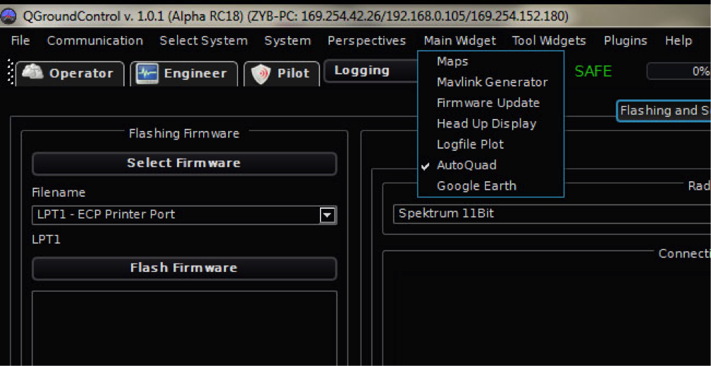
Open QGC, and choose “AutoQuad” from the main widget menu:

QGroundControl(QGC)의 Autoquad 버전은 ESC32의 설정을 변경하기 위해 포함된 위젯를 갖고 있습니다.

Putty를 이용한 command line interface(CLI)를 사용하기 위해서는 Max Levine´s forum post를 읽어주세요.

QGC를 오픈하고 메인 위젯 메뉴에서 "AutoQuad"를 선택합니다:


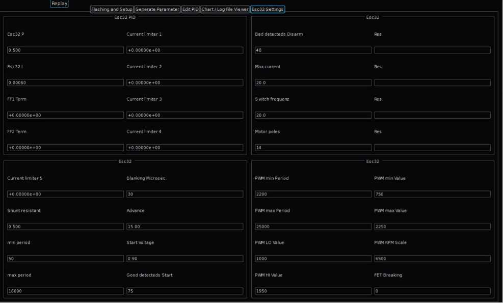
Then go to the tab “ESC32 settings”

그리고 "ESC32 settings"으로 이동합니다.


On the left side of the screen you can see the “Link ESC32” Tab:

화면의 왼쪽에서 여러분은 "Link ESC32" 탭을 볼 수 있습니다.


Connect UART adapter to ESC32 and computer and choose the UART adapter you are using and click connect.

ESC32와 컴퓨터를 UART 어댑터로 연결하고 여러분이 사용하는 UART 어댑터를 선택하고 "connect"를 클릭합니다.

When you connect the ESC to UART, it will go into disarmed state (Red LED blinking). Try and click “arm” – the ESC green LED should light up. If there is a main power source and motor hooked to the ESC you can run the motor by clicking “Start” and the motor will run at low duty (Remove props always when working with your multirotor)

여러분이 ESC와 UART를 연결하였을 때 이는 disarmed 상태로 갈 것입니다(적색 LED 깜박임). "arm"을 클릭합니다 - ESC 녹색 LED가 켜져야만 합니다. 만일 메인 전원이 연결되어 있고 모터가 ESC에 연결되어 있다면 여러분은 "Start"를 클릭하는 것으로 모터를 작동시킬 수 있으며 모터는 낮은 duty로 회전할 것입니다(여러분의 multirotor와 작동시킬 때 항상 프롭을 제거하세요).

Now you can alter the parameters in ESC32, but

여러분은 지금 ESC32의 파라미터를 변경할 수 있습니다 그러나

Make sure you don’t change parameters unless you know how the different parameters affect operation. Certain parameter combinations can be fatal for the ESC and motor!

만일 여러분이 서로 다른 파라미터들이 동작에 어떻게 영향을 줄 지를 모른다면 파라미터를 변경하기 마세요. 어떤 파라미터들의 조합은 ESC와 모터에 치명적일 수 있습니다!

Refer to the User configurable parameters section for more information on what each parameter controls.

각각의 파라미터들의 무엇을 조절할 지에 대한 추가적인 정보를 위해서 User configurable parameters를 참조하세요.


When parameters have been altered, you can upload them to ESC32 by clicking “write config”

파라미터들이 변경되면 여러분은 "write config"를 클릭함으로써 ESC32에 이들 값을 업로드할 수 있습니다.


User configurable parameters:

Generally, no parameters will need to be changed for normal out of the box PWM operation.  However, there are various parameters that can be set. Each parameter is a single numerical value.

일반적으로 어떠한 파라미터들은 정상적으로 바로 사용할 수 있는 PWM 동작을 위해서 변경할 필요가 없습니다. 그러나 설정될 수 있는 다양한 파라미터들이 있습니다. 각 파라미터들은 독립적인 수치입니다.

Note that some combinations of parameters can cause damage to your motor or ESC.  It is recommended to leave most values at their default values unless you are sure of how they impact function and operation.

파라미터들의 어떤 조합은 여러분의 모터와 ESC의 손상을 야기할 수 있음을 기억하세요. 만일 여러분이 이들이 기능과 동작에 어떤 영향을 줄지 알지 못한다면 디폴트 값으로 대부분의 값을 남겨두는 것을 추천합니다.

If you want to use the ESC32 with other FCs like MultiWii, APM2 (or Open Pilot Revo w/ APM firmware) or DJI NAZA please read the comments concerning certain values.

만일 여러분이 ESC32를 MultiWii, APM2 (혹은 Open Pilot Revo w/ APM firmware) 혹은 DJI NAZA와 같은 다른 FC들과 함께 사용하기를 원한다면 관련된 어떤 값의 주석문을 읽어주세요.

ParameterFactory DefaultDescription
   
STATUP_MODE0This is the run mode that the ESC defaults to when first powered on.
0 == normal open loop operation,
1 == closed loop RPM mode,
2 == closed loop thrust mode (not yet implemented)
BAUD_RATE230400The UART baud rate.  Allowable range 9600 to 921600
   
PTERM0.5The P term for the RPM PI controller
ITERM0.0006The I term for the RPM PI controller
   
FF1TERM0.0Feed forward terms used for the RPM controller.  Closed loop RPM mode will not function until FF1 & FF2 terms have been set.
FF2TERM0.0These values should be calculated using the esc32Cal program with the –r2v option
   
CL1TERM0.0CL1TERM through CL5TERM are used by the virtual current limiter which will not function until they are set.
CL2TERM0.0If CL1TERM through CL5TERM is not set, a PI controller will be used for current limiting instead.
CL3TERM0.0CL1TERM through CL5TERM can be calculated using the esc32Cal program with the –cl option.
CL4TERM0.0 
CL5TERM0.0 
   
SHUNT_RESISTANCE0.5This parameter should NOT be changed from the factory default!!! (Value in milliohms)
   
MIN_PERIOD50

The minimum commutation period allowed in microseconds : 20KHz

MAX_PERIOD12000

The maximum commutation period allowed in microseconds : 83.3Hz 

   
BLANKING_MICROS30The number of microseconds to ignore back EMF after a commutation.
   
ADVANCE15The amount of timing advance in electrical degrees.  There are 60 electrical degrees in a commutation cycle.  This value can be set from 0 to 30 degrees.
START_VOLTAGE1.1The amount of voltage presented to the motor during startup. Allowable range is 0.1v to 3.0v
GOOD_DETECTS_START75Once started, the number of good, in order zero crossings needed to be detected before the motor is considered to be in the running state.
BAD_DETECTS_DISARM48The number of missed zero crossing detects allowed before the ESC considers the motor not to be running at which point will go into the disarmed state.
   
MAX_CURRENT20The maximum amount of current in amps that the ESC will allow.  Current is dynamically regulated.  Always set this value low and only increase it if you know what you are doing.
SWITCH_FREQ20The output PWM pulse frequency used to power the motor windings in KHz.  Valid range is from 4KHz to 64KHz.
MOTOR_POLS14The number of magnetic poles used in the motor’s construction.  This value only needs to be set correctly if you want to use the RPM closed loop mode.
   
PWM_MIN_PERIOD2200The minimum period in microseconds that the ESC will consider an input PWM waveform to be valid.  Default value represents approx 450Hz. For MultiWii and ArduCopter APM (or Open Pilot Revo w/ APM fw) this value needs to be changed to 2000!
PWM_MAX_PERIOD25000The maximum period in microseconds that the ESC will consider an input PWM waveform to be valid.  Default value represents approx 40Hz
   
PWM_MIN_VALUE750The minimum input PWM pulse length in microseconds which the ESC will consider to be valid. For DJI Naza this value has to be 900!
PWM_LO_VALUE1000The input PWM pulse length in microseconds for the lowest throttle setting. For ArduCopter APM (or Open Pilot Revo w/ APM fw) this value needs to be changed to 1035!
PWM_HI_VALUE1950The input PWM pulse length in microseconds for the highest throttle setting.
PWM_MAX_VALUE2250The maximum input PWM pulse length in microseconds which the ESC will consider to be valid.
PWM_MIN_START1100The input PWM pulse length in microseconds at which the motor will be started.  Once running, the throttle can be brought as low as PWM_MIN_VALUE as long as the motor does not stall.
   
PWM_RPM_SCALE6500The scale of the input PWM pulse length.  In closed loop RPM run mode, PWM_LO_VALUE will indicate 0 RPM and PWM_HI_VALUE will indicate this RPM. Closed loop modes only!
FET_BRAKING0Turns on regenerative braking in closed loop modes (experimental),  
0 == off,
1 == on. Closed Loop modes only!!

Closed loop calibration

The ESC32 offers a closed loop RPM mode and a Closed loop thrust mode (Experimental). It requires calibration of the specific motor and prop you will be using.

ESC32는 closed loop RPM mode와 closed loop thrust mode(실험적인)를 제공합니다. 이는 여러분이 사용하고자 하는 특별한 모터와 프롭의 정밀한 조정을 요구합니다.

The calibration sequence is at an early stage in QGC and can be run under Linux and OSX from a terminal.

컬리브레이션 절차는 QGC에 초기 단계에 있고 이는 Linux와 OSX 하에서 작동시킬 수 있습니다.

Closed loop calibration instructions

Please be very careful running a calibration!
Your motors will perform certain patterns up to full power. Make sure to run these tests only in a secured environment!
Only use it in closed rooms or boxes where propellors can fly off without hurting anyone or damaging anything!

컬리브레이션은 매우 주의하여 진행하세요!
여러분의 모터들은 최대 파워까지 어떤 패턴으로 동작할 것입니다. 안전한 환경에서만 이들 테스트들이 진행되는지 확인해야 합니다! 프로펠러가 누군가 혹은 어떤 것을 다치게 하는 것 없이 동작할 수 있는 닫힌 공간이나 박스에서만 이를 사용하세요!

Refer to forum.autoquad.org for more details on how to perform closed loop calibration of ESC32 under Linux, OSX or from within QGC.

'Radio Control > ESC' 카테고리의 다른 글

ESC32 V2 메뉴얼 - Calibrations  (0) 2020.05.19
ESC32 - config  (0) 2020.04.29
ESC32 V2 메뉴얼 - Firmware Flashing  (0) 2020.04.23
ESC32 V2 메뉴얼 - Connections & Wiring  (0) 2020.04.03
BitWizard ESC의 소개  (0) 2018.12.03
Posted by Nature & Life
Radio Control/ESC2020. 4. 23. 21:45

ESC32 V2 Flashing Quick Guide


Preparations:
Make sure you have a correctly compiled *.hex file at hand.
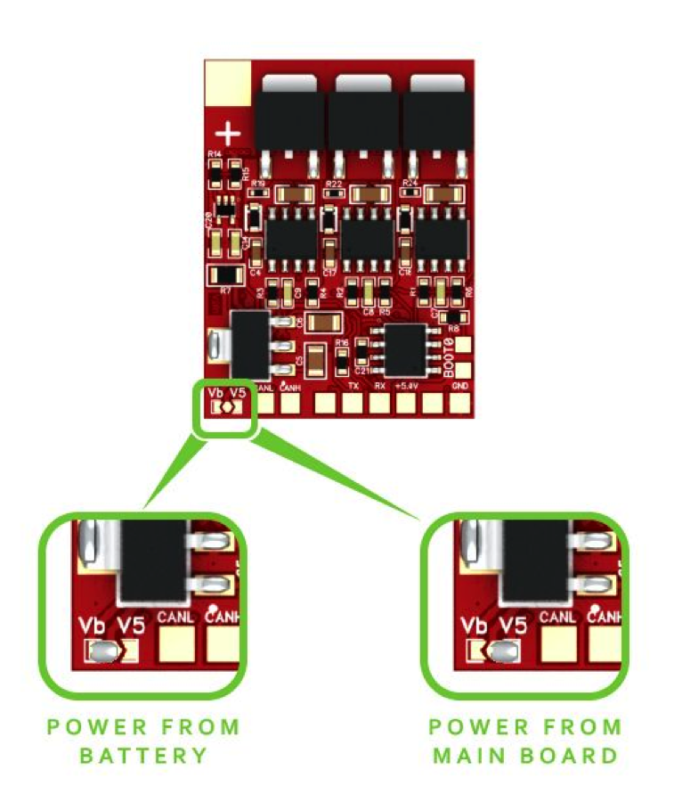
ESC32 needs to have the headers for the FTDI/USB adapter and boot jumper soldered – also don’t forget to set the solder jumper for the power supply (either 5V or Vb)
Connect your FTDI/USB adapter and the boot jumper, then power up the ESC. Read more…

여러분은 지금 올바로 컴파일된 *.hex 파일을 갖고 있는지 확인하세요.

ESC32는 FTDI/USB 어댑터를 위한 헤더와 남땜되어질 boot 점퍼를 갖고 있습니다 - 또한 전원을 위한 점퍼 설정하는 것을 잊지 마시기 바랍니다(5V 혹은 Vb 둘 중의 하나).

여러분의 FTDI/USB 어댑터와 boot 점퍼를 연결하고 ESC에 전원을 인가합니다.

In the AQ QGC select the “Engineer” tab with the AutoQuad Main Widget. Select “Flashing and Setup”

AQ QGC에서 AutoQuad 메인 위젯에서 "Engineer 탭을 선택하고 "Flashing and Setup"를 선택합니다.

In the “Flashing Firmware” part of the screen select your firmware you want to flash, select the appropriate COM port and click on “Flash Firmware”.

"Flashing Firmware"라는 화면에서 여러분이 플래시 하기 위한 펌웨어를 선택하고, 적당한 COM 포트를 지정하고 "Flash Firmware"를 클릭합니다.

In the message field above the Version number you should see the process of the upload, followed by a confirmation that flashing was performed successfully and the ESC will be rebooted.

버전 숫자 위의 메시지 란에서 여러분은 업로드의 과정을 보고 플래시가 성공적으로 실행되었는 지의 확인이 이어지고 ESC는 다시 부트될 것입니다.

To make sure everything went fine, disconnect the ESC from the power source and the FTDI/USB, close and reopen the QGC and connect your ESC again.
Open the “ESC32 Settings” tab, click on “Connect” and see if all values and settings are fine.

모든 것이 잘 되었는지를 확인하기 위해서 ESC에서 전원과 FTDI/USB 어댑터을 끊고, QGC를 닫았다 다시 실행시키고 ESC를 다시 연결합니다.

"ESC32 Settings" 탭을 열고 "Connect"를 클릭하고 모든 값들과 설정이 보이는지 확인합니다.

If you prefer a CLI (command line interface) via Putty or similar, follow the instructions in Max Levine´s forum post.

만일 여러분이 Putty 툴이나 유사한 것을 이용해서 CLI(command line interface)를 선호한다면 Max Levine´s forum post에 명령을 따라합니다.

You can now proceed with the ESC32 parameter configuration.

'Radio Control > ESC' 카테고리의 다른 글

ESC32 - config  (0) 2020.04.29
ESC32 V2 메뉴얼 - Configuration & Modes  (0) 2020.04.24
ESC32 V2 메뉴얼 - Connections & Wiring  (0) 2020.04.03
BitWizard ESC의 소개  (0) 2018.12.03
VESC 하드웨어(v4.x) 설정 메뉴얼  (0) 2018.01.24
Posted by Nature & Life
Radio Control/ESC2015. 12. 4. 12:02


다음은 AutoQuad의 오픈 소스 32 bit ESC(Electronic Speed Controller) Version2의 설명입니다.


Why the need for specialized ESCs:

왜 고급 ESC가 필요할까요:


Most standard ESCs are not designed for multirotor applications. Most ESCs are build and configured with an airplane application in mind, they are programmed to increase and decrease the throttle command towards the motor in a gentle way for obvious reasons. A motor fast accelerating and decelerating in an airplane or helicopter would either break the gears or put great stress on the prop and airframe.


대부분의 표준 ESC는 멀티로터에 사용하기 위해서 설계되지는 않았습니다. 대부분의 ESC들은 애초에 비행기에 맞도록 만들어지고 고안되었습니다. 그들은 분명한 이유 등으로 스로틀 명령으로 모터의 속도를 부드럽게 올리고 내리도록 프로그램되었습니다. 비행기나 헬리콥터에서 모터의 빠른 가속과 감속은 기어를 파괴하거나 기체의 프로펠러(Prop.)에 큰 손상을 주기 때문일 것입니다.


A multirotor is different. We would rather have a total linear curve and able to change the motor speed, and thus the thrust, as fast as possible to achieve a perfectly stable platform.


멀티로터는 다릅니다. 우리는 오히려 전체적으로 선형 커브를 갖도록 하여 모터 속도를 변화시키는 것이 가능하도록 하였기 때문에 완전하게 안정적인 비행을 성취가능한 빨리 추력을 낼 것입니다.


While the current ESCs used in most multrotor applications work considerably well, there is a lot of room for improvement. Using the same ESC but loading it with dedicated optimized firmware will increase the handling and stability of your multirotor greatly.


대부분의 멀티로터 응용에서 사용되어진 현재의 ESC들은 상당히 잘 동작하지만 여기에는 많은 개선의 여지가 있습니다. 같은 ESC를 사용하여 적용되어진 최적화된 펌웨어를 로딩하는 것은 여러분의 멀티로터의 조종성과 안정성을 크게 증가시킬 것입니다.


AutoQuad and most other flight controllers will benefit from ESCs that can operate at PWM frequencies of at least 400hz and are stripped from a controlled throttle curve.


AutoQuad와 대부분의 다른 비행제어기(FC)들은 적어도 400Hz의 PWM 주파수에서 동작가능한 ESC로부터 잇점을 누릴 것이고 기존의 스로틀 커브로부터 탈피하게 될 것입니다.


That's where the ESC32 comes in, a superior 32 bits ESC with a lot of interfaces and room for future enhancements.


이것이 ESC32가 나온 이유이며, 이 최상의 32 비트 ESC는 다양한 인터페이스를 지원하며 미래의 개선을 위해서 많은 리소스가 남아 있습니다.


Specifications for Version 2

      • STM32F103 72MHz 32bit ARM

      • All N-FET design with gate drivers

      • 2S through 5S battery voltage

      • Option to power logic side via UART or PWM IN +5v

      • CAN transceiver hardware support onboard

      • Firmware written completely in C

      • Cortex SWD connector pads for real-time debugging

      • Communications ports: PWM IN / UART / I2C / CAN Bus

      • Communications protocols: PWM IN / CLI / binary / 1-wire / CAN / I2C**

      • 4KHz to 64KHz PWM out

      • Current sensing / limiting with real shunt resistor

      • Virtual current limiter

      • Regenerative braking (experimental)

      • Closed loop control modes

      • Lot of available RAM / FLASH for experimentation and development

      • ** I2C drivers have not yet been written


'Radio Control > ESC' 카테고리의 다른 글

대표적인 상업용 VESC 구입처  (1) 2018.01.22
PX4ESC의 스펙  (0) 2015.12.08
RapidESC, 오픈 소스 펌웨어 개발 사이트  (0) 2014.06.19
RapidESC FAQ's  (0) 2014.06.11
RapidESC Flashing  (0) 2014.06.03
Posted by Nature & Life


AutoQuad 6 Flight Controller


What makes the AutoQuad flight controllers special?


무엇이 AutoQuad 비행제어기(FC)를 특별하게 만들까요?


Besides using top quality sensors and MCU, AutoQuad differs in its approach of using sensor calibration techniques and calculating the magnetic profile of the entire multirotor creating the ultimate stable flying and navigation experience.


최고 양질의 센서들과 MCU를 사용한 것 외에도 AutoQuad는 센서 보정 기술을 사용하는 그리고 최고의 안정된 비행과 조종 경험을 갖게 하는 전체 멀티로터의 자기 프로파일을 계산하는 접근 방식에서부터 차이가 납니다.


Summary of specifications of the AQ 6.x flightcontroller hardware

    • 2″ x 2.5″ main board with 4.5×4.5cm mounting hole pattern

    • Input voltage: 6.5v => 18v

    • 2 High efficiency DC/DC converters, separate power to flight controller logics and accessories.

    • STM32F407 32bit Cortex M4 microcontroller (1MB flash)

    • Standard Arm 10 pin 0.05″ pitch SWD connector

    • 14 general purpose PWM controllers / receivers (powered or un-powered)

    • Dedicated Spektrum satellite (remote receiver) 2.4Ghz R/C radio connector

    • uSD card slot driven by 4bit SDIO capable of 100Mb/s transfer (up to 32GB storage)

    • onboard uBlox LEA-6T GPS module with battery backup and time pulse capture

    • u.FL active GPS antenna connector

    • optional external bi-directional telemetry radio via standard 6 pin FTDI connector – powered up to 1A

    • I2C bus connector for I2C ESC’s (or other I2C devices)

    • X, Y Mag: HMC6042

    • Z Mag: HMC1041Z

    • X, Y Gyro: IDG500

    • Z Gyro: ISZ500

    • Accel: ADXL325

    • Pressure Sensor: MP3H6115A (optional 2. tube sensor)

    • Battery voltage monitor


Onboard IMU options:


Summary of capabilities of the AQ 6.x firmware

    • Fly extremely stable yet offer full dynamic control to the pilot.

    • Limit flying angles.

    • Mavlink 1.0x compatible protocol, Ground Stations for Win, Mac, Linux & Android

    • Very accurate position hold, depending on GPS reception a hold within 15-30 cm is possible.

    • Altitude override (ascend / descend) during position hold with controlled vertical speed.

    • Full mission flight, speed, heading and 'loiter time' is settable.

    • Return to home position, altitude is also recorded during home position set.

    • POI (point of interest), autonomous circling around given coordinates

    • Heading Free flight mode, Follow Me, Click & Go (needs exp. firmware)

    • Radio loss detection and event triggering.

    • Low battery detection and event triggering.

    • 2 axis gimbal control with pitch angle override on transmitter.

    • Gimbal working angle and response time is settable.

    • Gimbal servos can use 50Hz (analog) to 400+ Hz (digital) settable.

    • Radio options: Spektrum satellite (10 & 11bit), S-bus receiver, (C)PPM input, SUMD (Graupner) M-Link (Multiplex)

    • User Addon Waypoint recording and playback using transmitter switch.

    • User Addon External LED / Piezo signaling for status and events, MAVLink telemetry for Graupner HOTT radios


'Radio Control > Flight Controller' 카테고리의 다른 글

비행제어기(FC)의 역사와 종류(1)  (1) 2020.03.28
비행제어기(FC)란?  (0) 2017.03.07
AutoQuad 사이트에서 소소 코드를 확인하는 법  (0) 2015.12.02
AutoQuad란?  (0) 2015.11.29
APM v2.5 vs. Crius AIOP  (0) 2014.03.04
Posted by Nature & Life


AutoQuad는 오픈 소스 펨웨어 프로젝트입니다. 따라서 누구나 프로젝트를 다운로드 받아 수정하거나 개선하여 자신의 드론(Drone)에 업데이트 할 수 있고 자신의 구미에 맞게 비행을 즐길 수 있습니다.


AutoQuad 홈페이지에서 Source Code를 확인하는 법 ]


1) 메뉴에서 'Forum'를 클릭합니다. 

AutoQuad Forum


2) 메뉴에서 'AQ Downloads'를 클릭합니다.

AutoQuad and ESC32 Downloads


3) 다음 그림과 같이 하단의 아이콘 모음에서 선택합니다.


4) 모든 Source Code를 'Find file'을 클릭하여 확인하거나 다운로드 할 수 있습니다.


'Radio Control > Flight Controller' 카테고리의 다른 글

비행제어기(FC)란?  (0) 2017.03.07
AutoQuad 6 비행제어기의 스펙  (0) 2015.12.02
AutoQuad란?  (0) 2015.11.29
APM v2.5 vs. Crius AIOP  (0) 2014.03.04
다양한 Multiwii 보드  (0) 2014.03.03
Posted by Nature & Life


ARM 기반에 32 비트 MCU(STM32 계열)을 사용하여 비행제어기 보드(Flight Control Board)와 ESC를 만든 AutoQuad 프로젝트를 소개합니다. MCU가 갖는 빠르고 강력한 이점 외에도 C언어 기반의 ESC를 포함한 완전한 오프 소스 프로젝트라는 것입니다.


AutoQuad is an Open Source firmware project with closed source hardware. It is aimed at providing a flight controller board with stabilization, dynamic flight and autopilot features. The community can enhance the AutoQuad code. The powerful hardware with a 32 bits MCU and a selection of the best IMU sensors form the base for the AutoQuad flight controller, the possibilities are endless and only limited by the imagination and skills of the coders.


AutoQuad는 비공개 하드웨어를 사용한 오픈 소스 펨웨어 프로젝트입니다. 이는 안정성과 역동적인 비행 그리고 자동 항법 특징을 갖는 비행 제어 보드를 공급하는데 목적이 있습니다. 이 커뮤니티는 AutoQuad 코드를 진보시킬 수 있습니다. 32 비트 MCU와 가장 훌륭한 IMU 센서들의 장착한 강력한 하드웨어로 AutoQuad 비행제어기의 기본을 갖추었습니다. 그 가능성은 무한하고 단지 코드를 프로그램하는 사람의 상상력에 의해서 제한될 뿐입니다.


The current code base is targeting multicopters up to 14 motors. However the platform is flexible and can be adapted to fixed wing or single rotor applications.


현재의 코드는 14 모터까지 장착한 멀티콥터를 목표로 합니다. 그러나 개발환경은 유연하고 고정익 혹은 단일 로터를 갖는 기체에도 적용될 수 있습니다.


AutoQuad has recognized the need for specially adapted speed controllers or ESC’s. During the initial project setup, an 32bit ESC is developed: the ESC32. As with AutoQuad, the ESC32 is based on open source code, but closed source hardware.


AutoQuad는 특별한 속도 제어기 혹은 ESC를 요구해왔습니다. 초기 프로젝트 착수 동안에 32 비트 ESC가 개발되었습니다: ESC32. AutoQuad와 함께 사용되어지기 때문에 ESC32는 오픈 소스 코드 기반이지만 비공개 하드웨어에 사용되어집니다.


다음은 실제 프로젝트의 로드맵(Actual Project Timeline)니다.

Actual Project Timeline


'Radio Control > Flight Controller' 카테고리의 다른 글

AutoQuad 6 비행제어기의 스펙  (0) 2015.12.02
AutoQuad 사이트에서 소소 코드를 확인하는 법  (0) 2015.12.02
APM v2.5 vs. Crius AIOP  (0) 2014.03.04
다양한 Multiwii 보드  (0) 2014.03.03
Multiwii란?  (0) 2014.02.26
Posted by Nature & Life